This helps you quickly interpret patents by identifying the three key elements:
Problems solved by technology
Method used
Benefits of technology
[0017]A general object of the present invention is to provide improved methods and devices for reducing lift-induced drag on fluid dynamic structures.
[0018]Another object of the present invention is to provide a vortex-shaped wingtip—or other wing-like structure used to produce a normal force (lift)—that directs the vortex flow in such a way that the
Problems solved by technology
The drag on any fluid dynamic structure occurs due to shape, compressibility, and lift.
At speeds below the critical Mach number, drag due to lift is a major factor for any vehicle moving in a fluid.
The loss of pressure from the high pressure surface and the increase in pressure on the low pressure surface results in decreased lift.
Many of the above are not particularly efficient or useful for various reasons
Method used
Image
Click on the blue label to locate the original text in one second.
Reading with bidirectional positioning of images and text.
Examples
Embodiment Construction
[0031]For the purpose of promoting an understanding of the principles of the invention, reference will now be made to the embodiments illustrated in the drawings and specific language will be used to describe the same. It will nevertheless be understood that no limitation of the scope of the invention is thereby intended, such alterations and further modifications in the illustrated device and such further applications of the principles of the invention as illustrated therein being contemplated as would normally occur to one skilled in the art to which the invention relates.
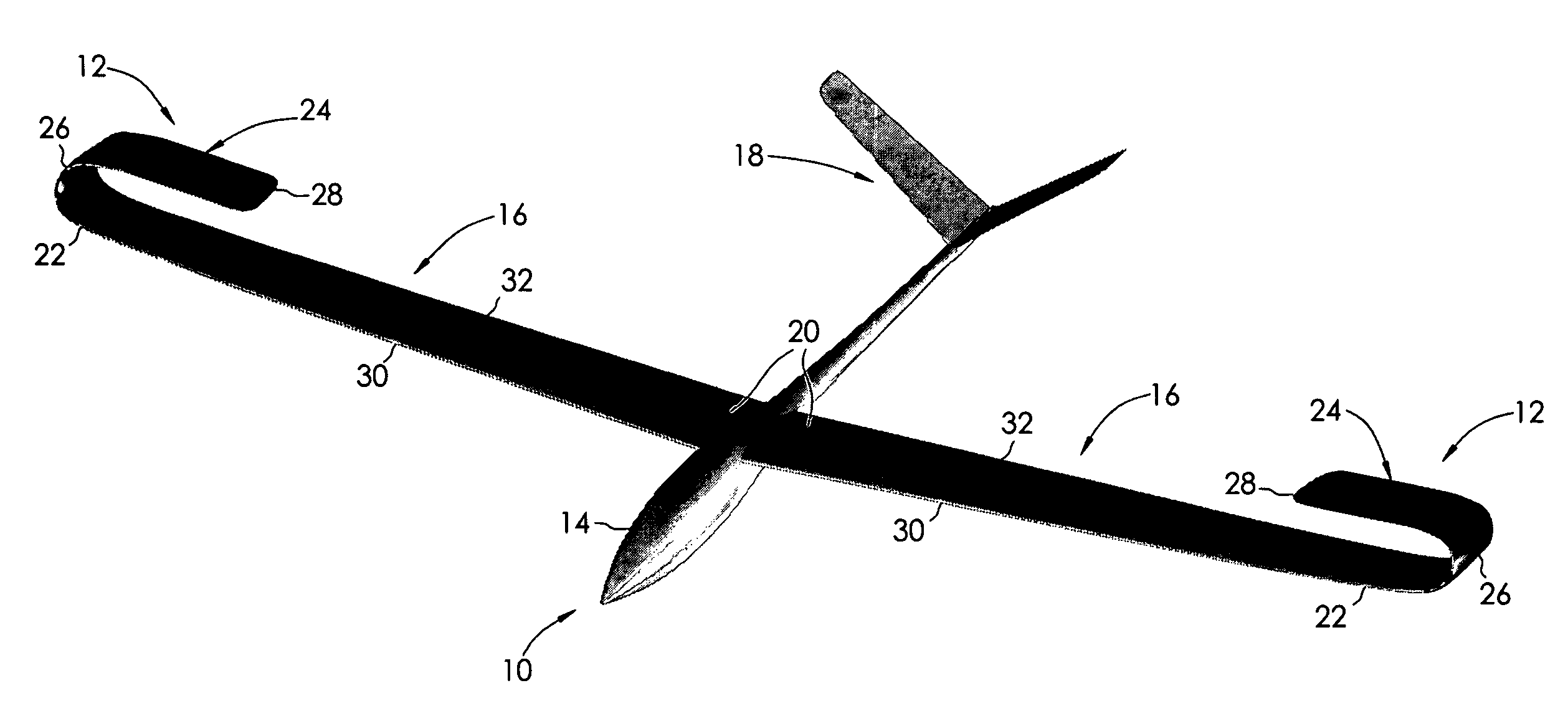
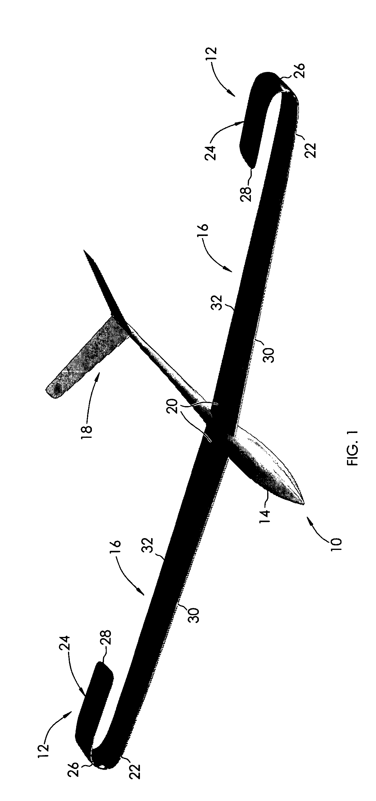
[0032]Three dimensional fluid dynamic structures typically terminate at an end point. In airfoils this termination is the wingtip. As indicated above, when fluid dynamic structures produce normal lift force, fluid flows axially from the high pressure side of the structure to the low pressure structure at the termination of the structure. This axial flow is spanwise to the lifting structure. The flow at the termin...
PUM
Abstract
A capped winglet comprising a helical portion having a smooth vertical curvature of 180°±approximately 20° from the plane of the unbounded end of a wing, and a generally planar cap contiguous with the helical portion of the winglet at the end of its curvature away from the wing, the cap having a free inboard end and a chord tapered toward the free end.
Description
BACKGROUND OF THE INVENTION[0001]This invention relates to fluid dynamic force development on moving and nonmoving fluid dynamic structures. The most common fluid dynamic structures to use this invention are airfoils such as wings and propellers and water based lifting and drag structures.[0002]The patents listed below constitute a representative listing of the prior art in this field:[0003]Pat. No.Issue DateInventor994,968Jun. 13, 1911Barbaudy1,050,222Jan. 14, 1913McIntosh1,841,921Jan. 19, 1932Spiegel1,939,682Dec. 19, 1933Fleming2,576,981Dec. 4, 1951Vogt2,775,419Dec. 25, 1956Hlobil2,805,830Sep. 10, 1957Zborowski3,270,988Sep. 6, 1966Cone4,050,397Sep. 27, 1977Vanderleest4,146,199Mar. 27, 1979Wenzel4,714,215Dec. 22, 1987Jupp et al.5,102,068Apr. 7, 1992Gratzer5,348,253Sep. 20, 1994Gratzer6,474,604Nov. 5, 2002Carlow[0004]The drag on any fluid dynamic structure occurs due to shape, compressibility, and lift. At speeds below the critical Mach number, drag due to lift is a major factor for...
Claims
Application Information
Patent Timeline
Application Date:The date an application was filed.
Publication Date:The date a patent or application was officially published.
First Publication Date:The earliest publication date of a patent with the same application number.
Issue Date:Publication date of the patent grant document.
PCT Entry Date:The Entry date of PCT National Phase.
Estimated Expiry Date:The statutory expiry date of a patent right according to the Patent Law, and it is the longest term of protection that the patent right can achieve without the termination of the patent right due to other reasons(Term extension factor has been taken into account ).
Invalid Date:Actual expiry date is based on effective date or publication date of legal transaction data of invalid patent.
IPC IPC(8): B64C23/06
CPCB64C23/065Y02T50/164B64C23/069Y02T50/10
Inventor ALFORD, JR., LIONEL D.CLAYMAN, JR., GARY J.