In-wheel suspension

a technology of in-wheel suspension and suspension arms, which is applied in the direction of resilient suspensions, vehicle components, and pivoted suspension arms, etc., can solve the problems of reducing the advantages of in-wheel suspension, the fact that the tire/wheel assembly can only move along the sliding sha

Inactive Publication Date: 2010-01-12
TOYOTA JIDOSHA KK
View PDF62 Cites 49 Cited by
  • Summary
  • Abstract
  • Description
  • Claims
  • Application Information

AI Technical Summary

Benefits of technology

[0005]It is an object of the invention to provide an in-wheel suspension that can change a toe-angle of a tire / wheel assembly when the tire / wheel assembly jounces / rebounds without reducing the advantages of the in-wheel suspension.
[0016]The invention provides the in-wheel suspension that can change the toe-angle of the tire / wheel assembly when the tire / wheel assembly jounces / rebounds.

Problems solved by technology

However, the tire / wheel assembly can actually move only along the sliding shaft when the tire / wheel assembly jounces / rebounds.
This prevents size reduction of a suspension and an increase in a space in a vehicle compartment, resulting in reduction of the advantages of an in-wheel suspension.

Method used


Image

  • In-wheel suspension
  • In-wheel suspension
  • In-wheel suspension

Examples


first embodiment

[0043]Accordingly, in the first embodiment, the pivot axes Y1 and Y2 are arranged such that the extended lines of the pivot axes Y1 and Y2 form a predetermined angle θ (see FIG. 4) that is greater than zero degree, instead of being arranged in parallel with each other, when viewed from the rear of the vehicle. As described later, the predetermined angle θ is a parameter that defines the characteristics of changes in the toe-angle of the tire / wheel assembly 10 when the tire / wheel assembly 10 jounces / rebounds. The predetermined angle θ is set such that the toe-angle is changed by an intended amount. For example, the predetermined angle θ may be set to a value greater than zero degree and less than five degrees (0°<θ<5°).

[0044]FIG. 4 illustrates the view for describing the principle of a change in the toe-angle, which is caused in response to the operation of the coupling member 60 (the arms 62, 64) when the tire / wheel assembly 10 jounces / rebounds. To facilitate the understanding of th...

second embodiment

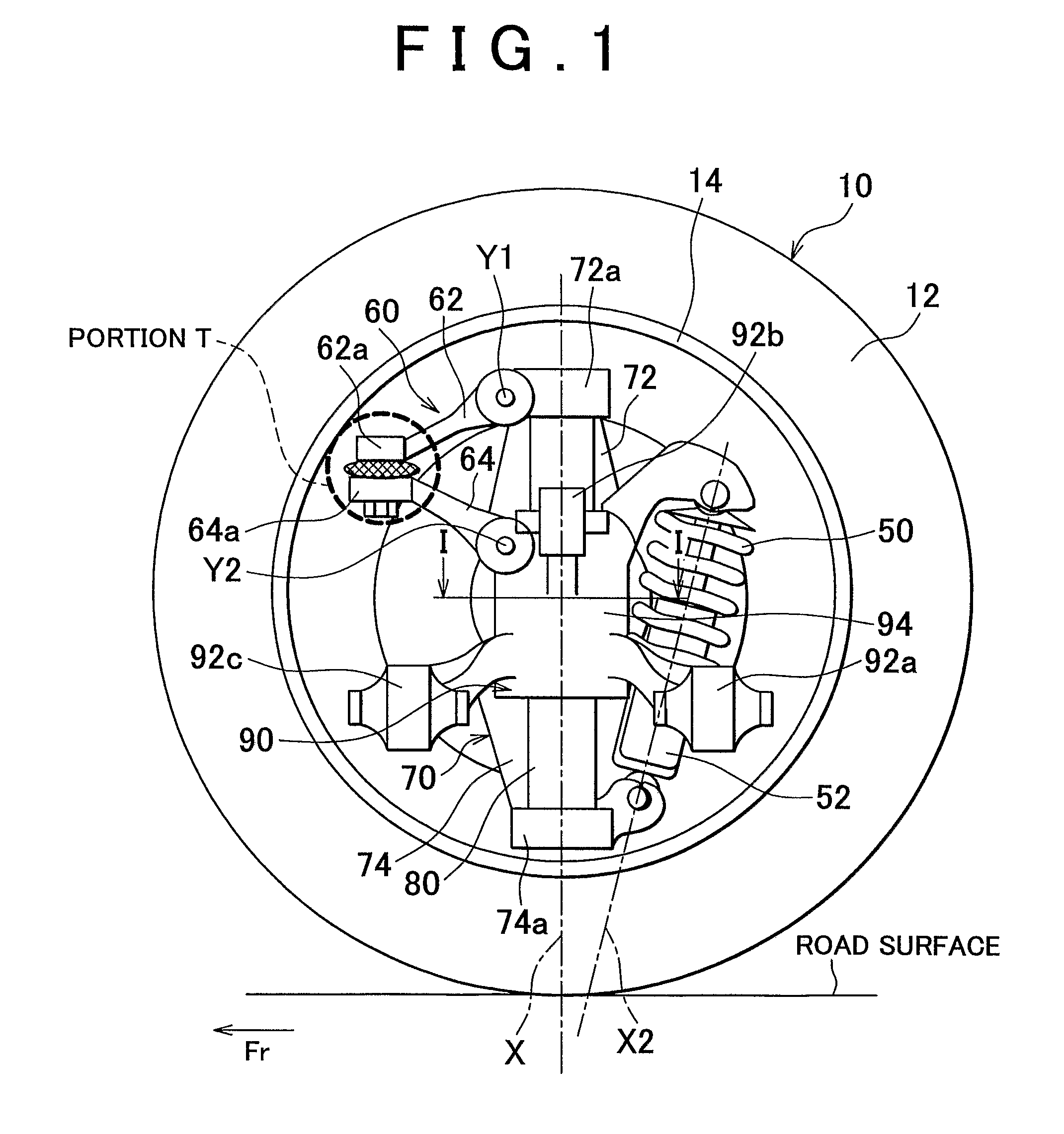
[0053]Similarly, the carrier 70 and the vehicle body-side member 90 are coupled with each other by the coupling member 60. The vertical / substantially vertical movement of the carrier 70 along the central axis X of the shaft member 80 is permitted, while its rotation on the central axis X of the shaft member 80 is restricted. In the second embodiment, as shown in FIG. 5, the pivot axes Y1, Y2 of the coupling member 60 (the arms 62, 64) extend in the longitudinal direction of the vehicle, as in the structure shown in FIG. 4. However, the pivot axes Y1, Y2 may extend in any directions, when viewed from the top of the vehicle. Thus, a certain degree of freedom in the vertical / substantially vertical movement of the tire / wheel assembly 10 with respect to the vehicle body is ensured.

[0054]In the second embodiment, the pivot axis Y1 of the arm 62 and the pivot axis Y2 of the arm 64 are arranged such that the extended lines of the pivot axes Y1 and Y2 form a predetermined angle θ that is gre...

third embodiment

[0059]the invention is realized according to the first embodiment or the second embodiment of the invention. According to the third embodiment, a toe-angle adjustment mechanism is provided to the in-wheel suspension according to the first embodiment or the second embodiment.

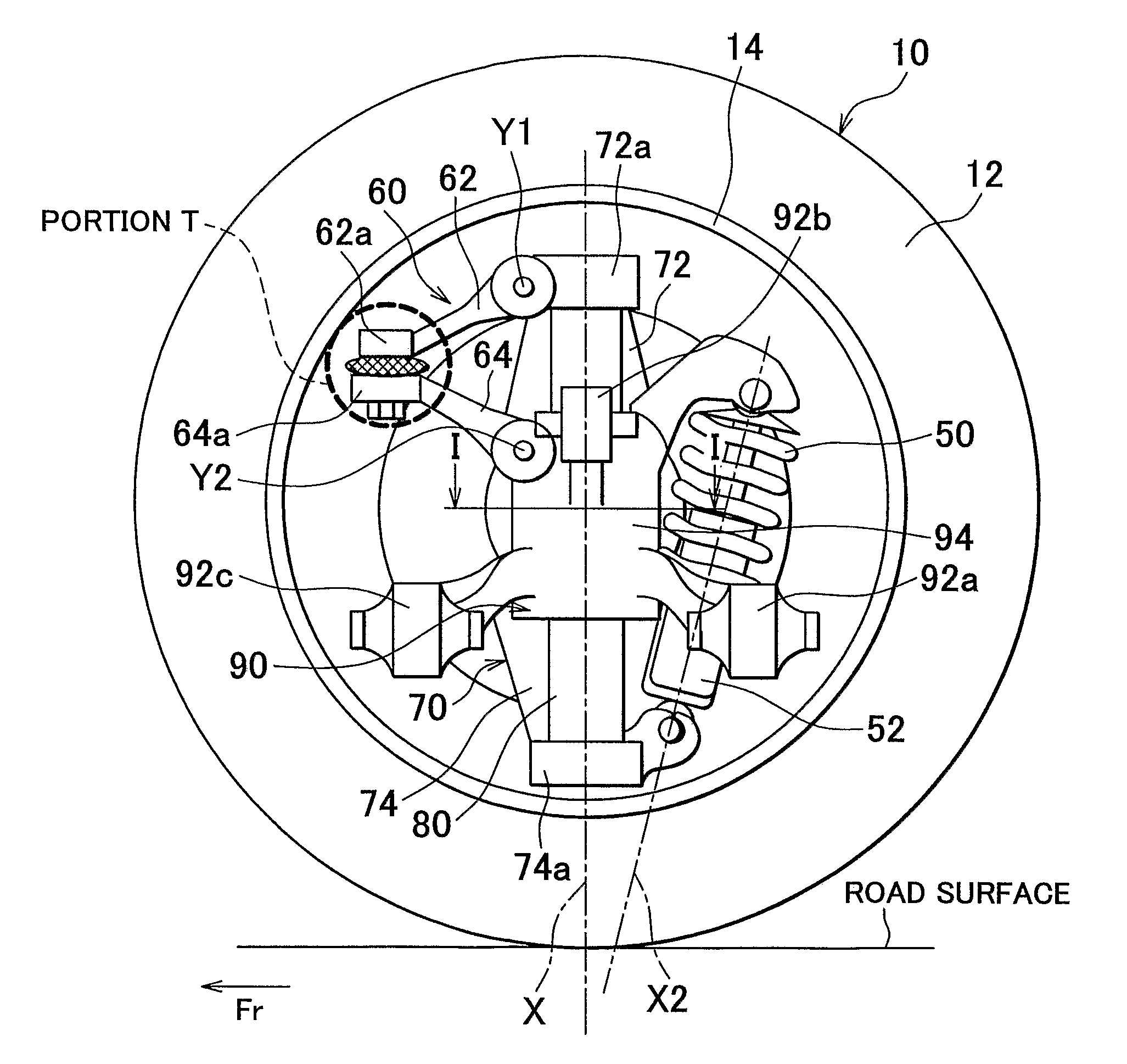
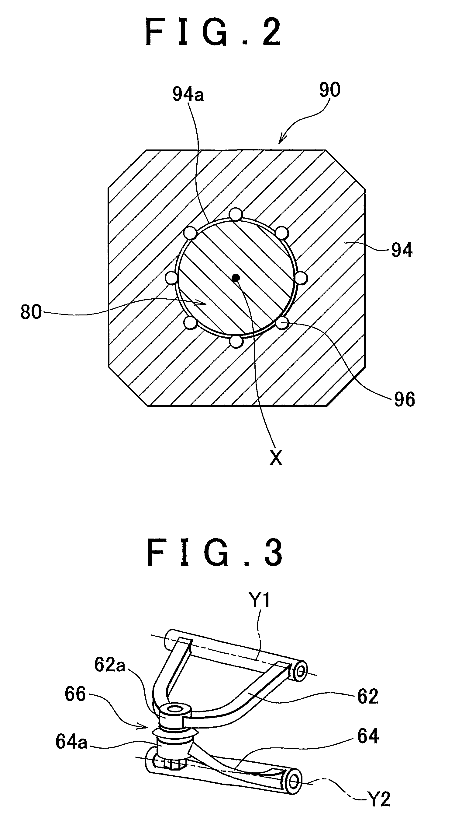
[0060]In the third embodiment, a toe-angle adjustment mechanism 30 is provided to the coupling member 60. FIG. 8 illustrates the enlarged cross-sectional view of a portion T in FIG. 1, and shows the toe-angle adjustment mechanism 30. In the example shown in FIG. 8, a ball joint 40 is used as the coupling portion 66 that couples the end portion 62a of the arm 62 with the end portion 64a of the arm 64 such that the end portions 62a, 64a can rotate with respect to each other. The ball joint 40 includes a ball stud 42. A screw shaft portion 42c is provided at the end portion of a tapered shaft portion 42b of the ball joint 40. The taper shaft portion 42b is fitted in a tapered hole formed on the arm 64 side. Then, a ...


PUM


Abstract

An in-wheel suspension including a tire / wheel assembly-side member that includes a tire / wheel assembly support member fixed to a tire / wheel assembly, a vehicle body-side member that supports the tire / wheel assembly support member such that the tire / wheel assembly support member can slide along a sliding axis X extending in the substantially vertical direction and rotate on the sliding axis X, and at least one of a spring element and an attenuation element that acts in accordance with sliding of the tire / wheel assembly support member. The in-wheel suspension further includes a coupling member that couples the tire / wheel assembly-side member with the vehicle body-side member, and that rotates the tire / wheel assembly support member in accordance with the sliding of the tire / wheel assembly support member.

Description

FIELD OF THE INVENTION[0001]The invention relates to an in-wheel suspension where main portions of suspension components are arranged in a wheel.BACKGROUND OF THE INVENTION[0002]Such an in-wheel suspension is described, for example, in Japanese Patent Application Publication No. JP-A-10-338009. The in-wheel suspension described in this publication includes a hub that supports a wheel. The wheel mainly includes a disc and a rim. The rim has a reference width and a reference diameter. The in-wheel suspension includes a wheel carrier that defines the rotational axis of the hub, and a guide member that guides the movement of the wheel carrier with respect to a support member in the axial direction. The support member includes fitting means for fitting the support member to a chassis of a vehicle. The wheel carrier is fitted to the guide member by a long-and-thin single bar, and slides according to the guidance by the guide member. The wheel carrier is prevented from rotating on the slid...

Claims


Application Information

Patent Timeline
Patent Type & Authority Patents(United States)
IPC IPC(8): B60G7/02B60G3/01B62D7/18B60G9/00B60G3/20B60G7/00
CPCB60G3/01B60G7/008B60G15/062B60G2204/148B60G2204/30B60G2204/4104B60G2204/421B60G2204/4232B60G2204/45B60G2206/50
Inventor YAMADA, MASAHIKO
Owner TOYOTA JIDOSHA KK
Why Eureka
Try Eureka