High voltage transformer with high magnetic leakage and dual high voltage output

a high-voltage transformer and high-voltage output technology, which is applied in the direction of transformer/inductance details, electrical equipment, inductances, etc., can solve the problem that the circuit cannot meet the requirement of resonance circuits partly, and achieve the effects of enhancing leakage inductance, widening the creepage distance of coil winding, and reducing the coupling

Inactive Publication Date: 2010-01-12
TAIPEI MULTIPOWER ELECTRONICS
View PDF8 Cites 4 Cited by
  • Summary
  • Abstract
  • Description
  • Claims
  • Application Information

AI Technical Summary

Benefits of technology

[0008]The primary purpose of the present invention is to enable the first core of the core set to pierce into the hollow support of the base and install isolation plates at the center of the hollow support. There are primary coils and a plurality of isolation channels for winding the first and second secondary coils placed on either side of the isolation plate at the center of the hollow support in orderly way. The first and second slots are opened between primary coils and the first and second secondary coils respectively, and cut into an internal through hole, while isolation plates are installed between adjacent slots to widen the coil winding creepage distance. When the second core of the core set is placed at one side edge of the hollow support, extensions at both ends of the second core go through both sides of the first core, together with the first and second protrusive parts between the two extensions that are installed within the first and second slots and combined with the first core to form multiple magnetic paths. Then the magnetic path, formed by magnetic flux of the primary coils flowing from the first and second protrusive parts to the first core, is considered as a bypass to generate magnetic leakage, thus mitigating the coupling effect between primary coils and secondary coils and enhancing leakage inductance.
[0009]The secondary purpose of the present invention is to further cover the base with a protection cover, inside which the first and second isolation plates are installed to separate the first and second secondary coils from the first and second protrusive parts so as to separate the two protrusive parts from the two secondary coils. This can prevent high voltage puncture from occurring because of close proximity of two protrusive parts of the second core to the two secondary coils. Enlargement of the creepage distance for coil winding can establish a safe distance, thus avoiding sparking phenomena (short-circuits) that may occur due to unsafe distance from the two protrusive parts of the second core to the two secondary coils, thus raising the operational efficiency of the transformer and extending its service life.

Problems solved by technology

With low leakage inductance, this circuit cannot meet the requirement of resonance circuits partly.

Method used


Image

  • High voltage transformer with high magnetic leakage and dual high voltage output
  • High voltage transformer with high magnetic leakage and dual high voltage output
  • High voltage transformer with high magnetic leakage and dual high voltage output

Examples


Embodiment Construction

[0018]The preferred embodiments of the present invention are illustrated in detail by the examples and accompanying drawings given below in order for members of the review committee to further understand the objectives, appearance, configuration, devices, features and functions of the present invention.

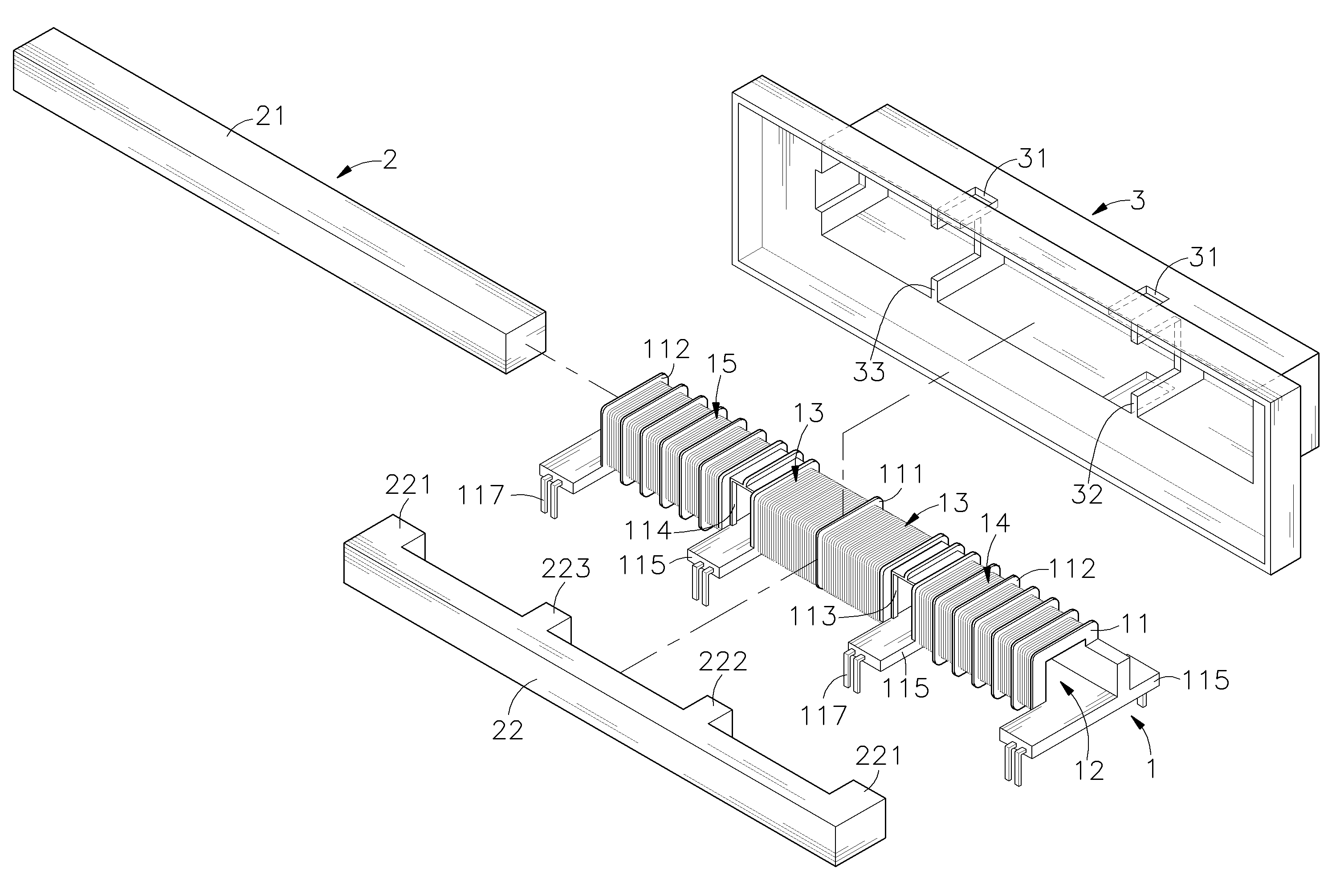
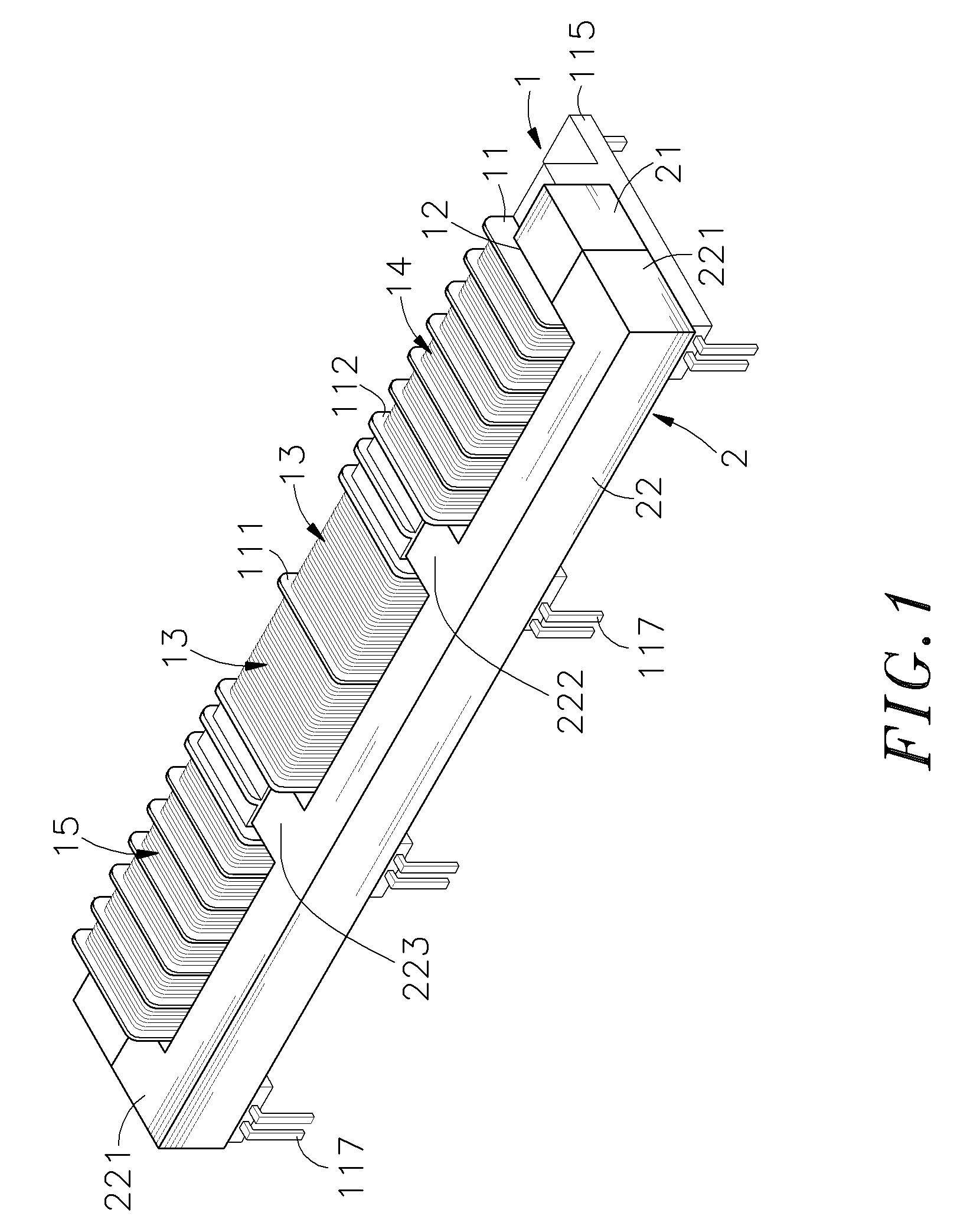
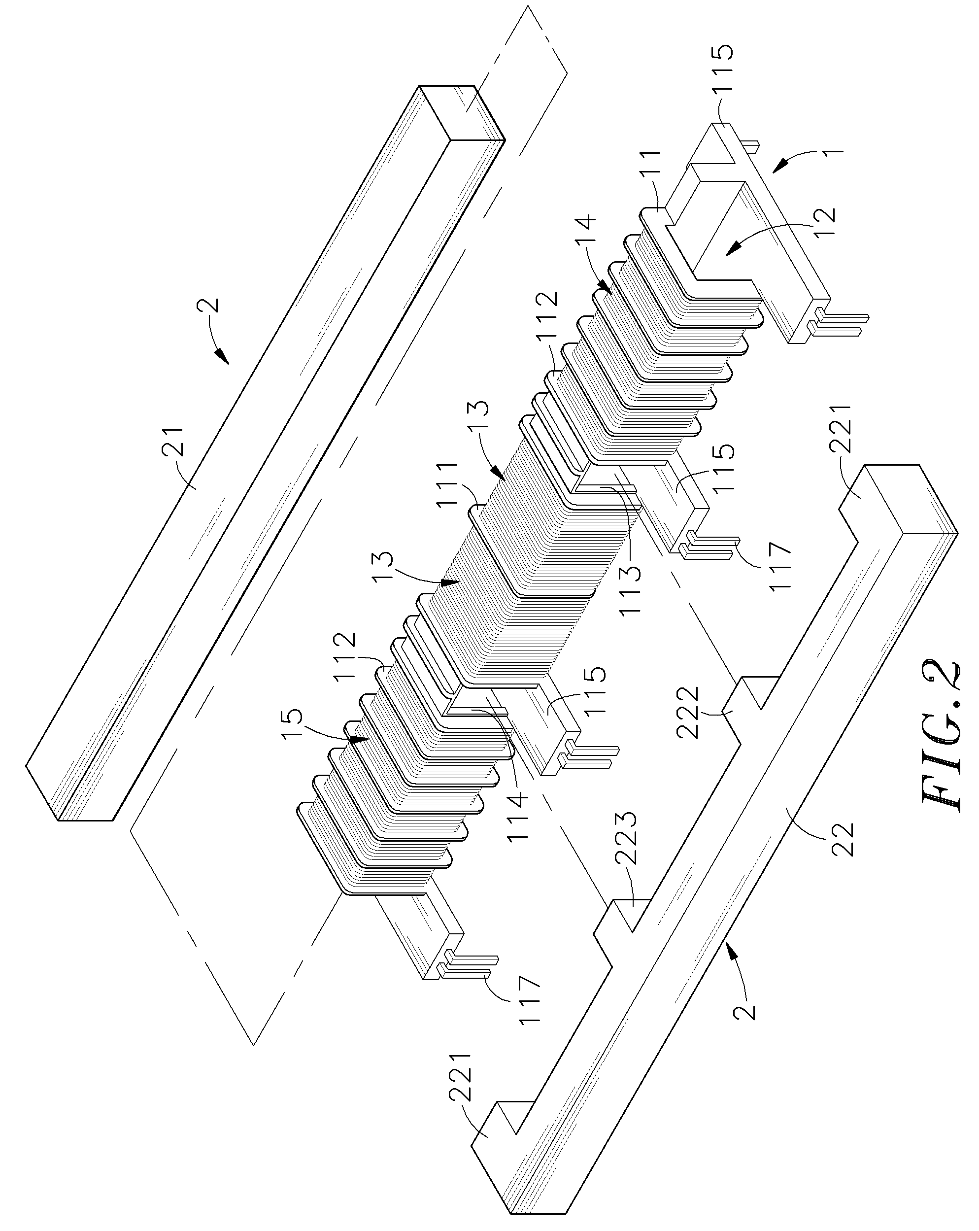
[0019]Refer to FIGS. 1, 2 and 3, which are the 3D appearance drawing, 3D breakdown drawing and upward view drawing of the present invention respectively. These figures show that the high voltage transformer with high magnetic leakage and dual high voltage output of the present invention comprises a base 1 and a core set 2 (in this example, the main components and features will be described in detail as follows), wherein:

[0020]The base 1 contains a hollow support 11 around which coils can be wound, and there is a through hole for the core set 2 to pierce inside the hollow support 11. A central isolation plate 111 is placed roughly at the center on the surface of the hollow support 11. ...


PUM

PropertyMeasurementUnit
leakage inductanceaaaaaaaaaa
breakdown structureaaaaaaaaaa
voltageaaaaaaaaaa

Abstract

The present invention relates to a high voltage transformer with high magnetic leakage and dual high voltage output, comprising a base and a core set, wherein the base contains a hollow support into which a first core of the core set pierces, and primary coils are wound on both sides of the hollow support, while a plurality of isolation channels is installed for winding first and second secondary coils on external sides of primary coils. First and second slots are opened between the primary coils and the first and second secondary coils respectively, and both slots cut into an internal through hole. When a second core of the core set is placed at one end of the hollow support, extensions at both ends of the second core go through both sides of the first core, together with first and second protrusive parts between the two extensions that are installed within the first and second slots and combined with the first core to form multiple magnetic paths.

Description

[0001]This application is a Continuation-In-Part of my patent application Ser. No. 10 / 905,088, filed on Dec. 15, 2004.BACKGROUND OF THE INVENTION[0002]1. Field of the Invention[0003]The present invention provides a high voltage transformer with high magnetic leakage and dual high voltage output, particularly, a high voltage transformer that can mitigate coupling effect between primary and secondary coils to enhance leakage inductance through design of dual bypass flux, and can enlarge the creepage distance between primary and secondary coils through the design of isolation plates on the protection cover, for the purpose of providing dual high voltage output.[0004]2. Description of Related Art[0005]Refer to FIGS. 7 and 8, which show the breakdown structure and appearance of a high voltage transformer in conventional use. As shown clearly in these figures, the high voltage transformer for conventional use contains a support A, within which there is a jack A1. A first core B1 of a core...

Claims


Application Information

Patent Timeline
Patent Type & Authority Patents(United States)
IPC IPC(8): H01F27/02
CPCH01F27/326H01F38/10H01F27/306
Inventor YANG, CHING-SHENGWU, SU-HUAWANG, SHU-CHEN
Owner TAIPEI MULTIPOWER ELECTRONICS
Why Eureka
Try Eureka