

Power plugging device with a function of releasing charges from electric surges
a technology of power plugging device and charge surge, which is applied in the direction of overvoltage protection resistor, emergency protective arrangement for limiting excess voltage/current, coupling device connection, etc., can solve the problem of resistance dropping rapidly in an extremely short time, and achieve the effect of avoiding complex wiring
- Summary
- Abstract
- Description
- Claims
- Application Information
AI Technical Summary
Benefits of technology
Problems solved by technology
Method used
Image

Examples
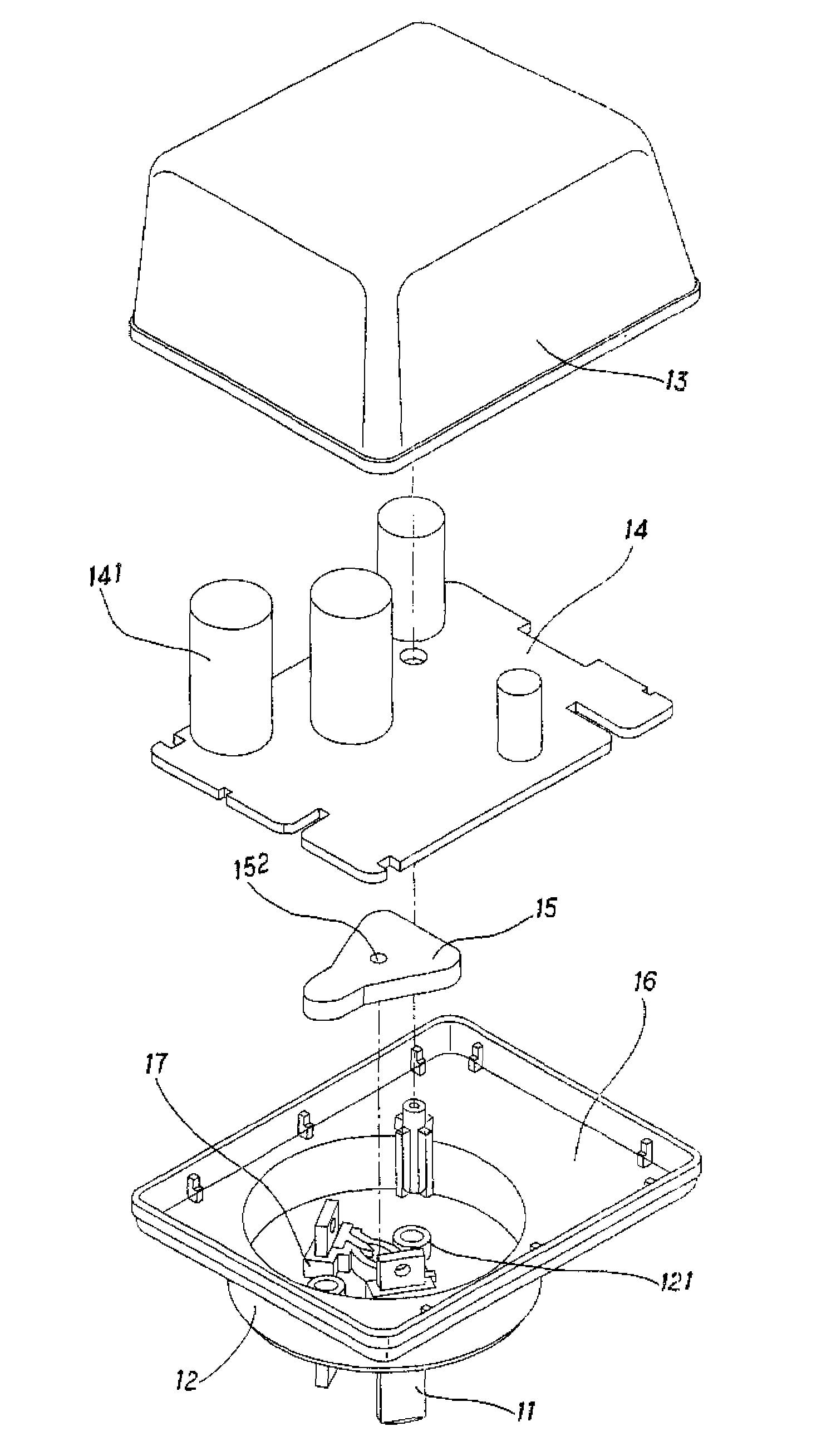
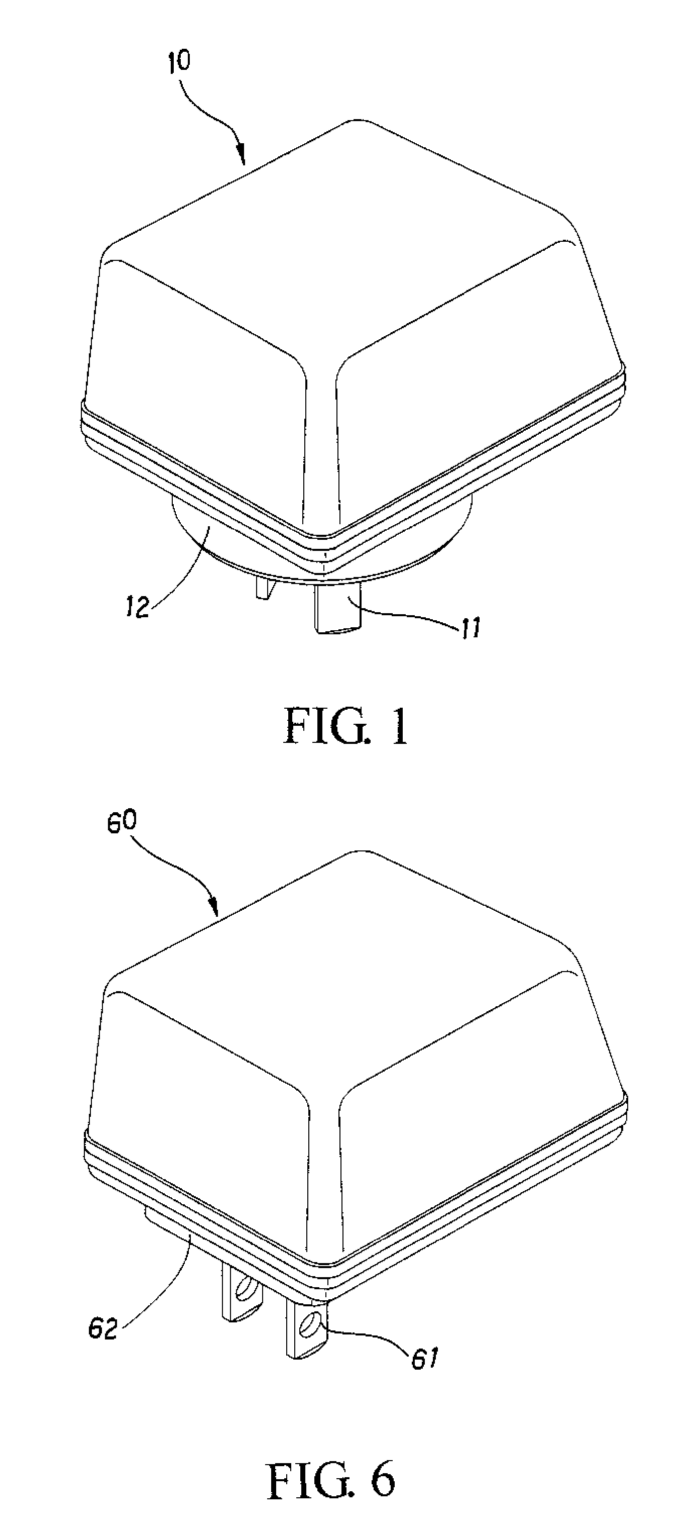
first embodiment
[0012]FIG. 1 is a perspective view schematically illustrating the power plugging device with a function of releasing charges from electric surges according to the present invention;
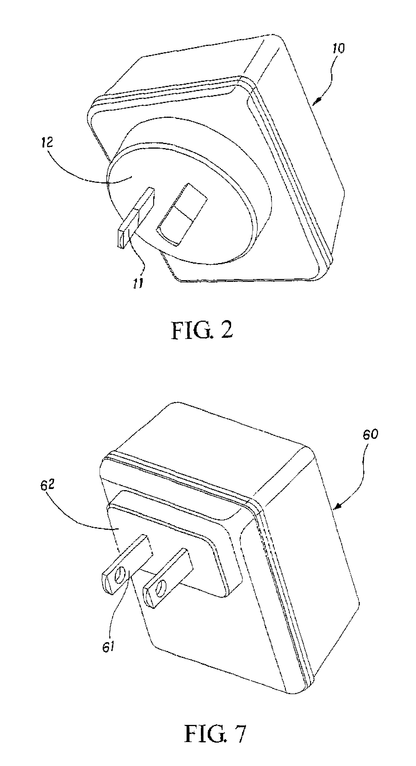
[0013]FIG. 2 is another aspect of the embodiment shown in FIG. 1;
[0014]FIG. 3 is an exploded view of the first embodiment;
[0015]FIG. 4 is an exploded view of a partial structure of the first embodiment;
[0016]FIG. 5 is a perspective view of a partial combined structure of the first embodiment;
second embodiment
[0017]FIG. 6 is a perspective view schematically illustrating the power plugging device with a function of releasing charges from electric surges according to the present invention;
[0018]FIG. 7 is another aspect of the embodiment shown in FIG. 6;
[0019]FIG. 8 is an exploded view of the second embodiment;
[0020]FIG. 9 is an exploded view of a partial structure of the second embodiment; and
[0021]FIG. 10 is a perspective view of a partial combined structure of the second embodiment.
PUM
 Abstract
Description
Claims
Application Information