Heating apparatus

a technology of heat exchanger and heat exchanger, which is applied in the direction of lighting and heating apparatus, indirect heat exchangers, and steam generation using hot heat carriers. it can solve the problems of substantial reduction of heat energy contributed, and reduction of heat exchange efficiency of latent heat exchanger

Inactive Publication Date: 2010-01-19
NORITZ CORP
View PDF24 Cites 37 Cited by
  • Summary
  • Abstract
  • Description
  • Claims
  • Application Information

AI Technical Summary

Benefits of technology

[0079]The heating apparatus of the present invention has such advantageous effect as high heat exchange efficiency even in small size.

Problems solved by technology

Careful studies to solve the problems described above brought about a conclusion that drain considerably causes reduction of heat exchange efficiency of a latent heat exchanger.
Thus, heat of the combustion gas is used for revaporization of the drain, resulting in reduction of heat energy contributed to temperature rising of water in the heat exchanger.
In addition, when adhering to the surface of the latent heat exchanger, a large amount of drain decreases heat transfer to inside of the heat exchanger, resulting in substantial reduction of heat exchange efficiency.
Therefore, the latent heat exchanger for use in the conventional heating apparatus of the latent heat recovery type is obliged to be made of a high corrosive-resistant and costly material, causing cost rising.
There have been no previous cases in which such a heat exchanger just described is employed as a latent heat exchanger of a combustion-type heating apparatus because it is generally thought to be difficult to miniaturize such a heat exchanger.
However, according to the studies by the inventors, the laminated heat exchanger has poor efficiency of discharging of drain, and thus, in order to employ as a latent heat exchanger of a combustion-type heating apparatus, the above-mentioned heat exchanger having a plurality of heat receiving tubes arranged in parallel is more suitable than one just described.

Method used


Image

  • Heating apparatus
  • Heating apparatus
  • Heating apparatus

Examples


Embodiment Construction

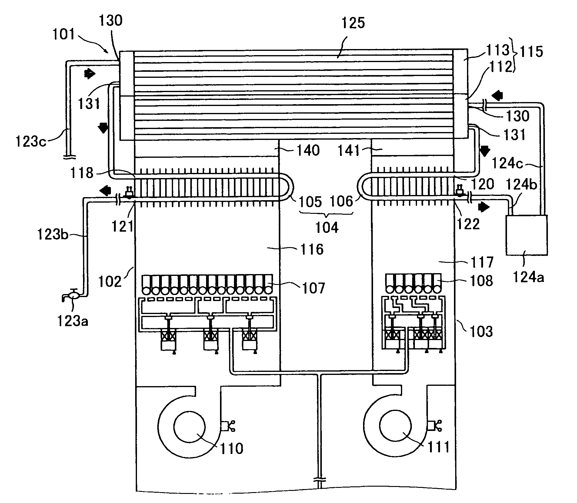
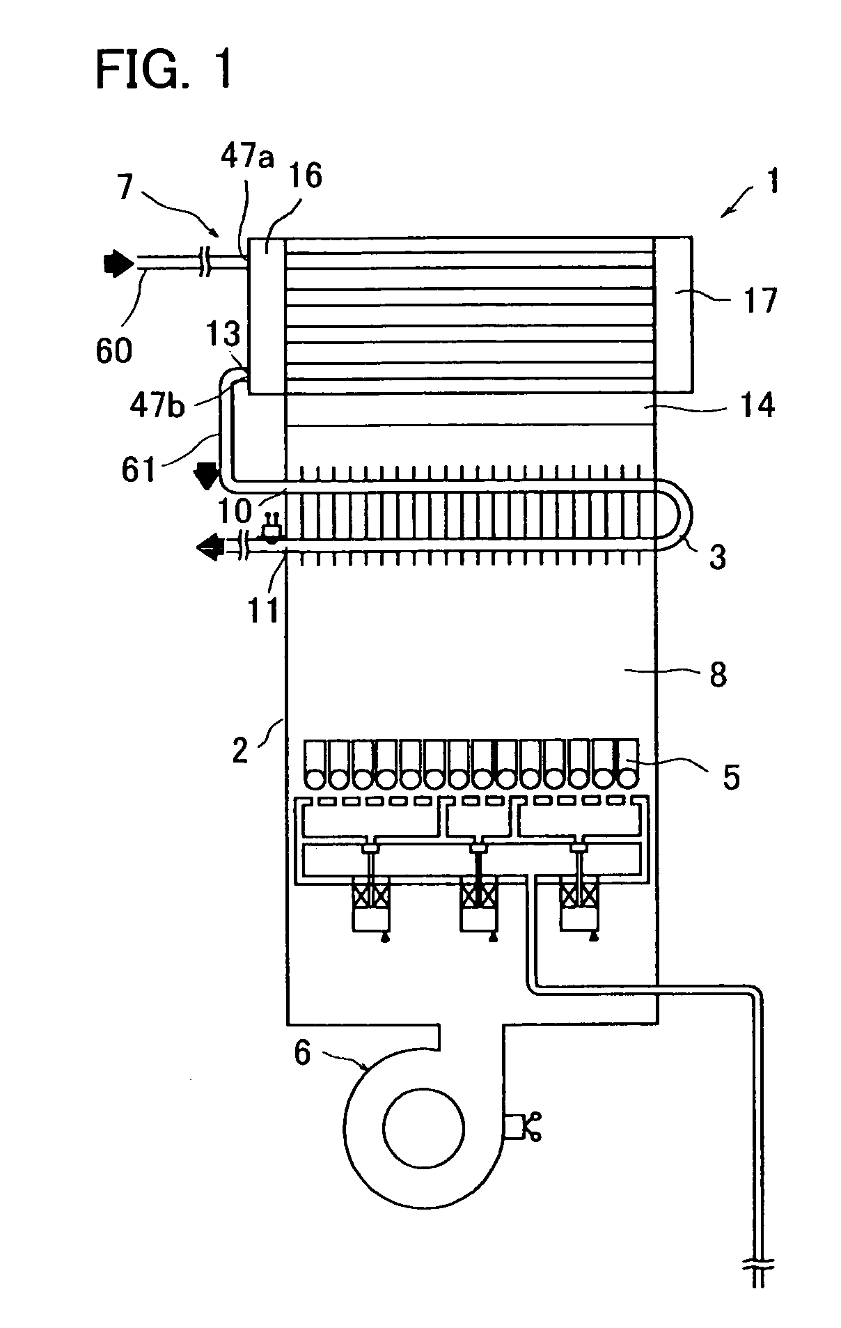
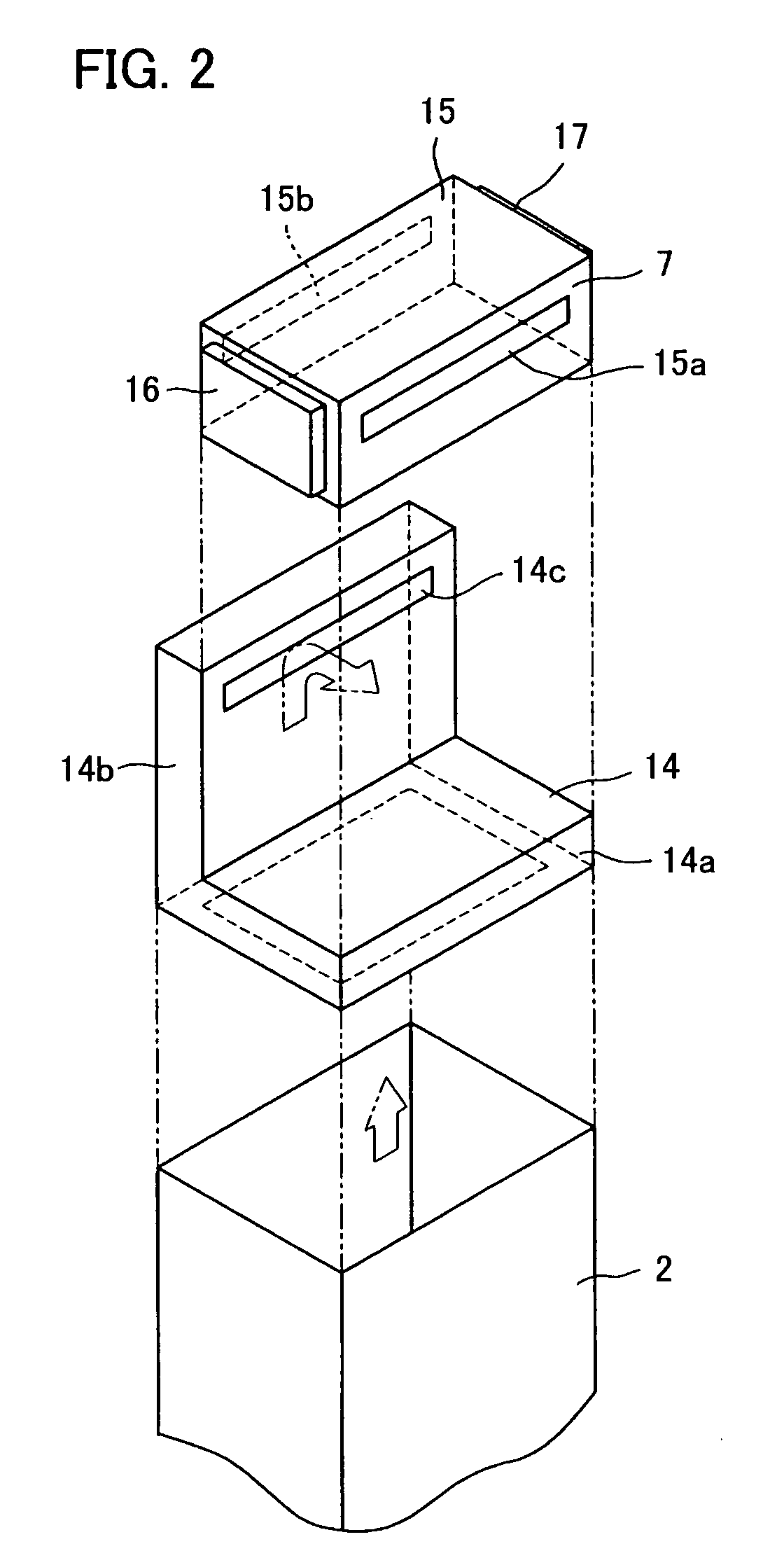
[0104]A combustion-type heating apparatus embodying the present invention will be described below in detail with reference to the accompanying drawings. FIG. 1 is a block diagram showing the heating apparatus of the present embodiment. FIG. 2 is an exploded perspective view showing the vicinity of a secondary heat exchanger of the heating apparatus shown in FIG. 1. FIG. 3 is a perspective view of the secondary heat exchanger and a gas-discharging member. FIG. 4 is an exploded perspective view of the secondary heat exchanger shown in FIG. 3. FIG. 5 is a cross-sectional view of the secondary heat exchanger as taken along A-A of FIG. 3. FIG. 6A is a schematic view showing arrangement of heat receiving tubes in the secondary heat exchanger shown in FIG. 3. FIG. 6B is a schematic view showing a modified example of arrangement of heat receiving tubes in the secondary heat exchanger shown in FIG. 3. FIGS. 7A and 8A each are a perspective view of a passage-forming member of the secondary he...


PUM


Abstract

A heating apparatus 1 includes a shell 2, a primary heat exchanger (sensible heat exchanger) 3, a burner (combustion means) 5, and a fan 6. A secondary heat exchanger (latent heat exchanger) 7 has a plurality of heat receiving tubes 18 arranged in parallel between a pair of headers 16 and 17, the heat receiving tubes 18 being fixed to tube plates 20. The heat receiving tubes 18 are bare tubes without fins and are arranged across flow of combustion gas. The number of the tubes 18 arranged vertically is less than the number of the tubes 18 arranged horizontally.

Description

CROSS-REFERENCE TO RELATED APPLICATION[0001]This application is a 371(c) National Stage of International Patent Application No. PCT / JP2005 / 005241 filed Mar. 23, 2005, which claims priority of Japanese Patent Application Nos. 2004-089439 and 2004-088402 filed Mar. 25, 2004, the disclosures of which are incorporated herein by reference.BACKGROUND OF THE INVENTION[0002]1. Technical Field[0003]The present invention relates to a heating apparatus using a burner, especially to a heating apparatus for heating water provided with a heat exchanger adapted to utilize (recover) latent heat of combustion gas.[0004]Herein, in the present application, the term “water” includes cold water and hot water, if not otherwise specified.[0005]2. Background Art[0006]A heating apparatus (also called a heat source equipment) using a burner for burning gas or liquid fuel is commonly used as heat source for a device such as a water heater or a bath heater. Recently, a combustion-type heating apparatus having ...

Claims


Application Information

Patent Timeline
Patent Type & Authority Patents(United States)
IPC IPC(8): F22B1/02F24H1/14F24H1/40F24H8/00F24H9/14F28D7/00
CPCF24H1/40F24H8/00F24H9/14F24H1/46F24H9/148F28D7/00Y02B30/102Y02B30/00
Inventor OOTOMO, ICHIROASAKURA, HIROSHIHORI, TOSHIHIROTAKEDA, NOBUHIROKIMURA, KAZUHIROTSUTSUMI, AKIRAFUJITA, TAKAYASUMORIKAWA, MASAKUNI
Owner NORITZ CORP
Why Eureka
Try Eureka