Eureka AIR delivers breakthrough ideas for toughest innovation challenges, trusted by R&D personnel around the world.

Riding type vehicle

a technology of riding type and transmission, which is applied in the direction of cycle equipment, transportation and packaging, cycle, etc., can solve the problems of deteriorating the function of cooling the inability to provide the exhaust duct, etc., and achieve the effect of improving the cooling of the v-belt type continuously variable transmission and reducing the size of the body cover

Inactive Publication Date: 2010-01-19
YAMAHA MOTOR CO LTD
View PDF8 Cites 10 Cited by
  • Summary
  • Abstract
  • Description
  • Claims
  • Application Information

AI Technical Summary

Benefits of technology

[0010]The present invention has been carried out in view of these circumstances, and it is an object thereof to provide both improved cooling of a V-belt type continuously variable transmission and downsizing of the body cover.
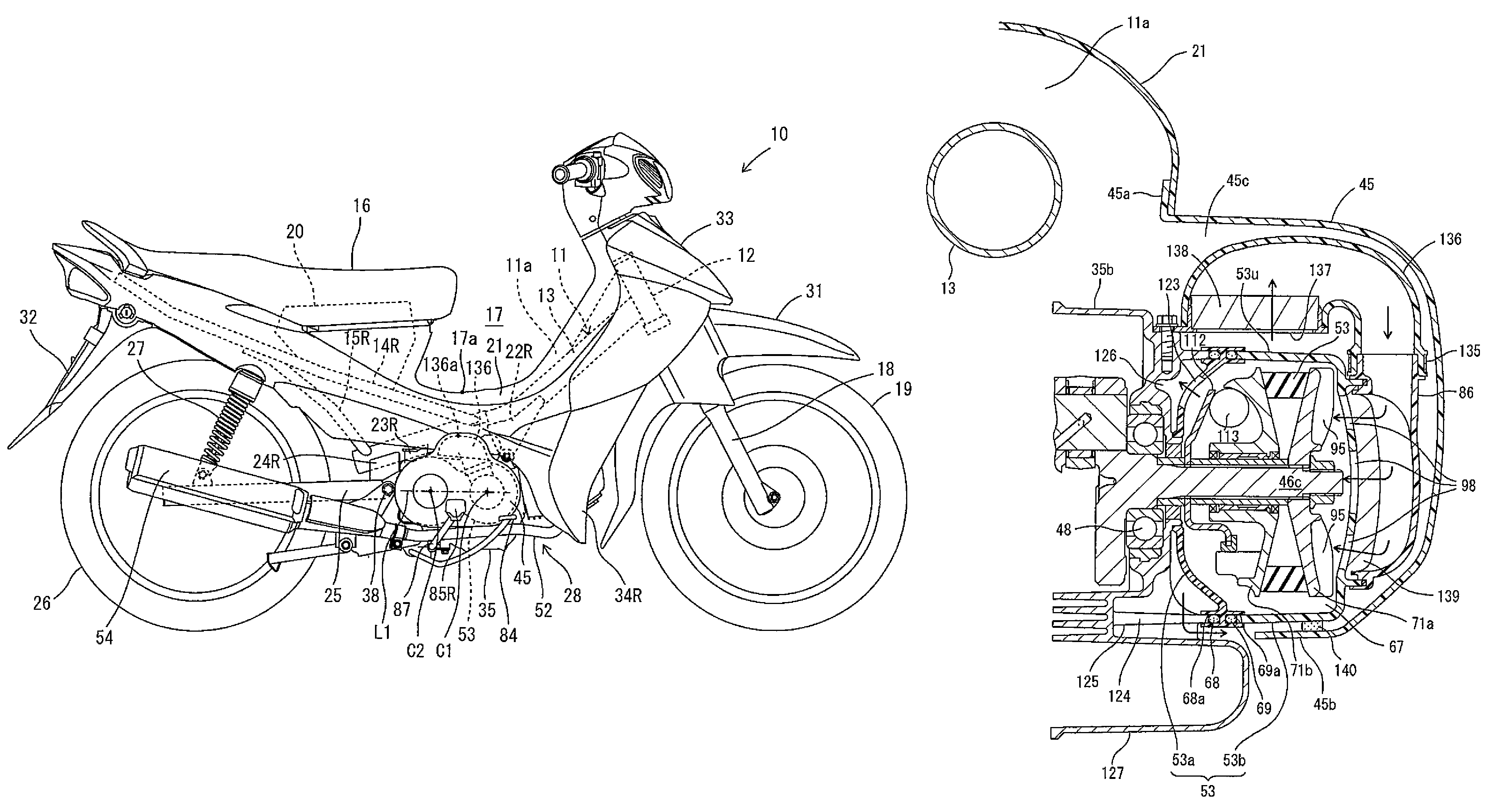
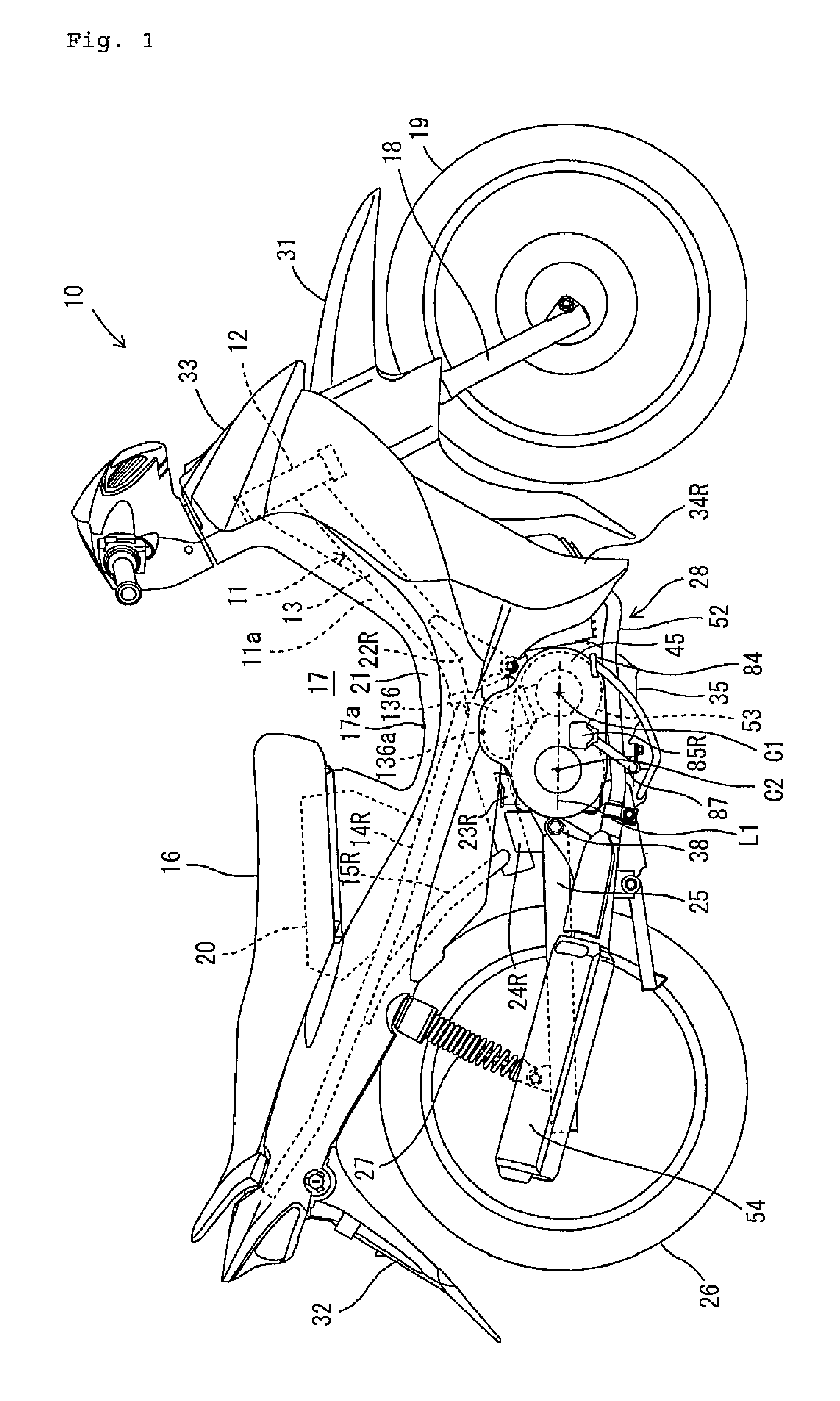
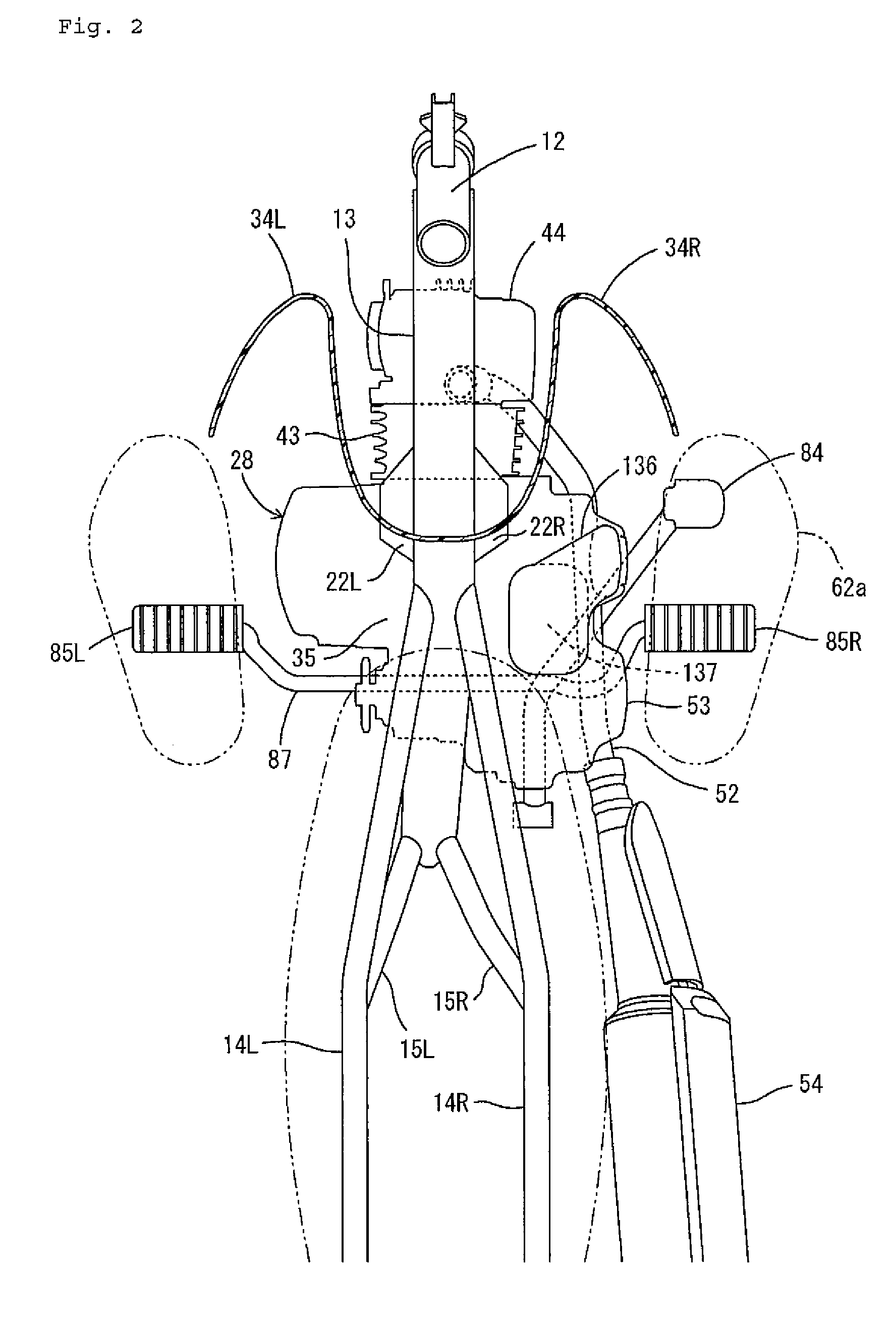
[0012]According to the invention, the air path communicating with the belt chamber is disposed at a space on the outer side in the vehicle width direction of the center tunnel and above the transmission case and therefore, the space is effectively utilized as a space of installing the air path. Therefore, even when the vehicle body cover is not upsized, an air path having a sufficient flow path sectional area is formed. Therefore, improved cooling of the V-belt continuously variable transmission and downsizing of the vehicle body cover are made compatible. Further, the upper end of the air path is lower than the lower end of the recessed space on the front side of the seat. Therefore, arrangement of the air path can be carried out or facilitated.
[0014]In the riding type vehicle, the air path communicating with the belt chamber is disposed at a space above the transmission case and therefore, the space is effectively utilized as the space of installing the air path. Therefore, improved cooling of the V-belt type continuously variable transmission and downsizing of the vehicle body cover are made to be compatible with each other. Further, the air path is not projected to an outer side in the vehicle width direction as much as the foot mounting member and therefore, slim formation of the vehicle is improved.
[0015]According to the invention, in a riding type vehicle including a V-belt continuously variable transmission, improved cooling function of the V-belt continuously variable transmission and downsizing of the vehicle cover are both provided.

Problems solved by technology

On the other hand, when the intake duct and the exhaust duct are decreased in diameter to downsize the body cover, a sufficient cross-section of the air flow path inside of the intake duct and the exhaust duct cannot be provided, and the function of cooling the V-belt type continuously variable transmission is deteriorated.

Method used


Image

  • Riding type vehicle
  • Riding type vehicle
  • Riding type vehicle

Examples


first embodiment

[0032]As shown by FIG. 1, a riding type vehicle according to the first embodiment of the invention is a motorcycle 10. The motorcycle 10 includes a body frame 11 and a seat 16 on which a passenger is seated. The motorcycle 10 is a so-called moped type motorcycle. That is, the motorcycle 10 is formed with a downward-recessed space 17 on a front side of the seat 16, and the passenger seated on the seat 16 straddles body frame 11. The ‘moped type’ mentioned here indicates only a shape of the vehicle, and does not limit the maximum speed, exhaust amount, the size of the vehicle and so on.

[0033]The riding type vehicle according to the invention is not limited to a moped but may be another type of motorcycle in which a fuel tank is disposed on a front side of the seat.

[0034]In the following description, the terms front, rear, left and right denote directions viewed from the perspective of a passenger seated on the seat 16. The body frame 11 includes a steering head pipe 12, a main frame 1...

second embodiment

[0119]According to the first embodiment, the intake duct 136 partitioning the intake path is arranged on the outer side in the vehicle width direction of the center tunnel 11a and above the transmission case 53. However, the air path arranged on the outer side of the center tunnel 11a and above the transmission case 53 is not limited to the intake path. According to a second embodiment shown in FIGS. 11-13, an exhaust path for exhausting air after having cooled CVT 30 is disposed on the outer side in the vehicle width direction of the center tunnel 11a and above the transmission case 53.

[0120]As shown by FIGS. 11 and 12, according to the embodiment, a connecting tube 96 is formed on a front side portion (portion on a side of the primary sheave 71) of the outer side case 53b of the transmission case 53, and is connected with an intake duct 134. An upstream side of the intake duct 134 is connected to an air chamber 130. The air chamber 130 is arranged on a rear side of the leg shield ...

third embodiment

[0134]In the first embodiment (refer to FIG. 9), body cover 21 and the cover 45 are formed separately and overlapped partially. Further, the intake duct 136 is arranged outward in the vehicle width direction as compared with the body cover 21. Also in the second embodiment (refer to FIG. 13), the body cover 21 and the cover 147 are formed separately and overlapped partially. Further, the exhaust duct 146 is arranged outward in the vehicle width direction as compared with the vehicle body cover 21. However, the body cover covering the center tunnel and the cover covering the duct may be formed integrally.

[0135]According to the third embodiment shown in FIG. 14, the body cover 21 and the cover 147 are formed integrally. In other words, the cover 147 forms a part of the body cover 21. Therefore, exhaust duct 146 is arranged outward in the vehicle width direction (a left and right direction of FIG. 14) as compared with the center tunnel 11a and positioned inward in the vehicle width dir...


PUM


Abstract

A riding type vehicle with improved cooling function of a V-belt continuously variable transmission and a compact body cover. A front side of a seat is partitioned with a space recessed to a lower side. The inside of a vehicle body cover is partitioned with a center tunnel. An engine unit is supported by a vehicle body frame on a lower side of the recessed space. The engine unit includes a transmission case having a belt chamber containing the V-belt continuously variable transmission. A footrest is arranged on an outer side in a vehicle width direction of the transmission case. An intake duct that guides air for cooling the V-belt type continuously variable transmission is disposed on an outer side in a vehicle width direction of the center tunnel and on an upper side of the transmission case.

Description

RELATED APPLICATIONS[0001]This application claims the benefit of priority under 35 USC 119 of Japanese patent application no. 2005-222919, filed on Aug. 1, 2005, and Japanese patent application no. 2006-182021, filed on Jun. 30, 2006, which applications are hereby incorporated by reference in their entirety.BACKGROUND OF THE INVENTION[0002]1. Field of the Invention[0003]The present invention relates to a riding type vehicle having a V-belt continuously variable transmission.[0004]2. Description of Related Art[0005]Motorcycles having a V-belt continuously variable transmission are well known (refer to, for example, JP-A-2002-130440).[0006]The V belt of a V-belt type continuously variable transmission increases in temperature during travel due to friction heat and the like. Hence, a method of forcibly cooling the V belt by supplying air to a belt chamber containing the V belt from outside is often used.[0007]The motorcycle disclosed in JP-A-2002-130440 includes a vehicle body frame su...

Claims


Application Information

Patent Timeline
Patent Type & Authority Patents(United States)
IPC IPC(8): B60K11/00B60K11/06B62J17/06B62J99/00B62J23/00B62M9/08F16H57/02F16H57/035F16H57/04
CPCF16H57/0415F16H57/0489B62K2202/00
Inventor ISHIDA, YOUSUKEOISHI, AKIFUMI
Owner YAMAHA MOTOR CO LTD
Why Eureka
Eureka Blog
Learn More