
Vehicle floor covering system

a floor covering and vehicle technology, applied in the field of floor covering systems, can solve the problems of reducing the likelihood of the joint being a trip point and/or the margins of the meeting edges curling, requiring a certain requiring some amount of installation time, so as to speed and facilitate installation, reduce the number of parts, and the appearance is nea

Active Publication Date: 2010-01-19
NAVISTAR CANADA
View PDF10 Cites 8 Cited by
  • Summary
  • Abstract
  • Description
  • Claims
  • Application Information

AI Technical Summary

Benefits of technology

"The present invention is a floor covering system for mobile vehicles that reduces the number of parts, simplifies installation, and provides a neater appearance. The floor coverings connect together without the use of separate joining strips or metal fasteners. Instead, the coverings have overlapping margins that interlock with each other, creating a flush joint appearance. The floor covering system is made of a single piece of synthetic material that has the necessary receptacles or formations for connection. The coverings can be easily installed and are supported by a foam layer underneath. The invention simplifies the process of covering the floor of a mobile vehicle and provides a more aesthetically pleasing appearance."

Problems solved by technology

That results in an acceptable appearance and reduces likelihood of the joint being a trip point and / or margins of the meeting edges curling.
However, thermal conductivity of the fasteners and the extrusion can cause the extrusion to feel cold in winter even when the occupant compartment is warm.
Moreover, the use of an extrusion and separate fasteners adds parts to the vehicle, requires some amount of installation time, and therefore adds to manufacturing cost.

Method used


Image

  • Vehicle floor covering system
  • Vehicle floor covering system
  • Vehicle floor covering system

Examples


Embodiment Construction

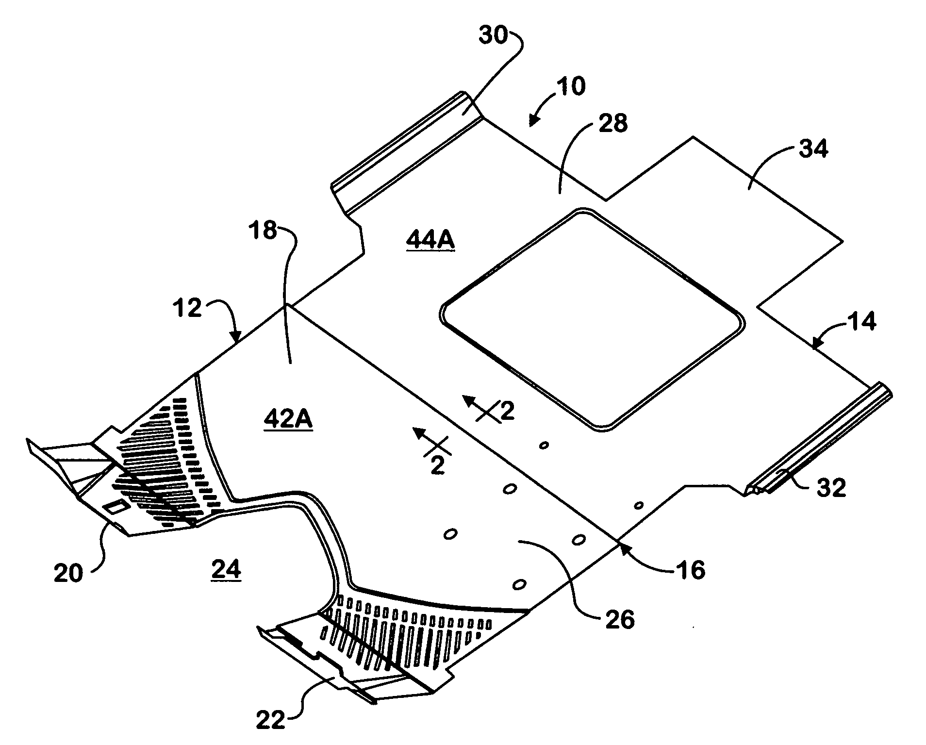
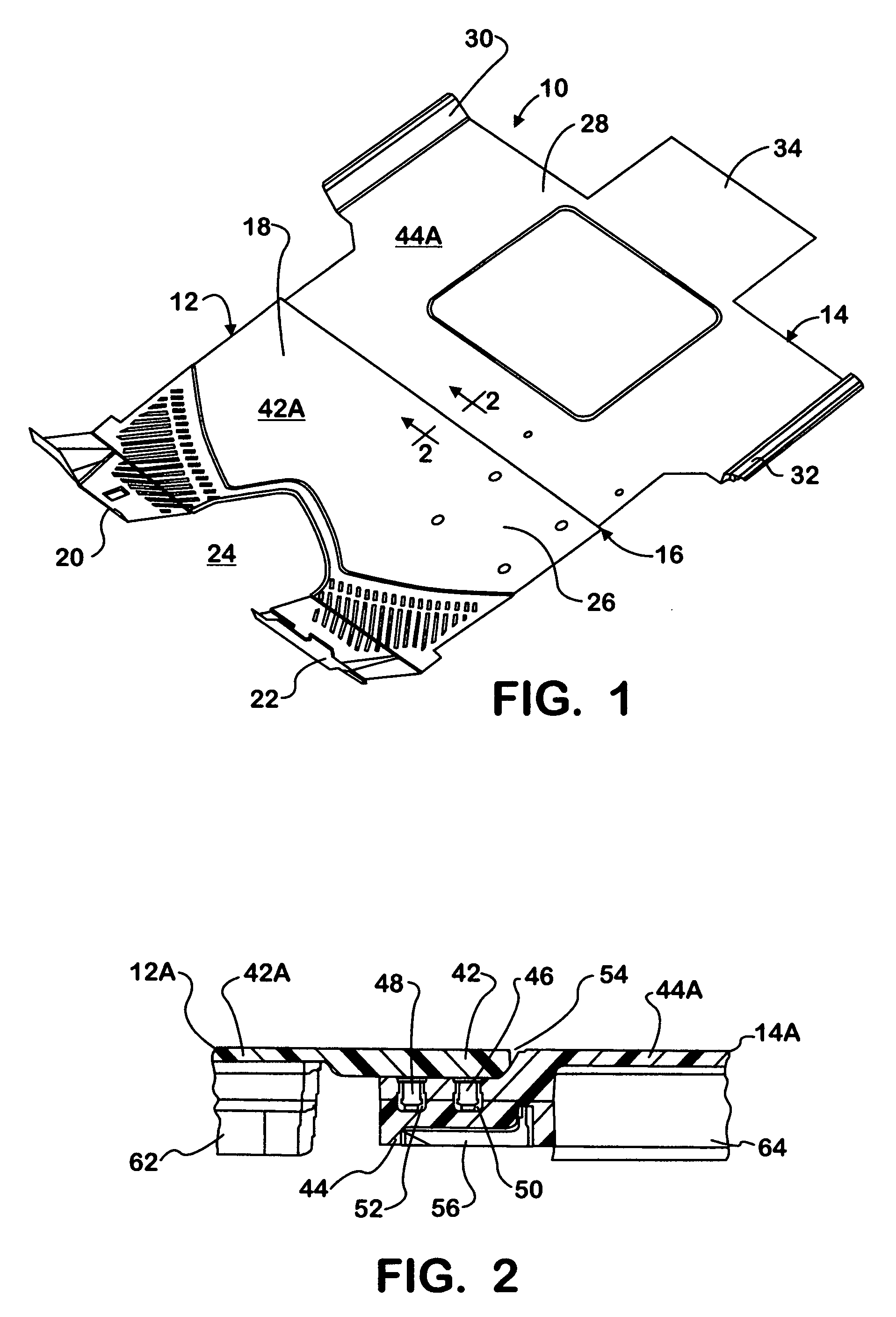
[0020]FIG. 1 shows a floor covering system 10 comprising a front floor covering 12 and a rear floor covering 14 that are connected together along a joint 16 that runs generally perpendicular to opposite sides. Front covering 12 comprises a generally flat zone 18 having a top surface immediately contiguous and extending forwardly from joint 16. The most forward portion of covering 12 comprises right and left zones 20, 22 having the inclined shapes shown to conform to the inclined lower portion of a dash panel (not shown in this Figure) of an occupant cab of a motor vehicle when the floor covering system is installed on the floor of the occupant compartment, leaving an open space 24 where a console / engine cover is located.

[0021]Front covering 12 covers a front zone of the occupant compartment floor where the driver and passenger seats are located. The reference numeral 26 identifies the approximate area occupied by the driver's seat although the seat itself is not shown and is install...


PUM


Abstract

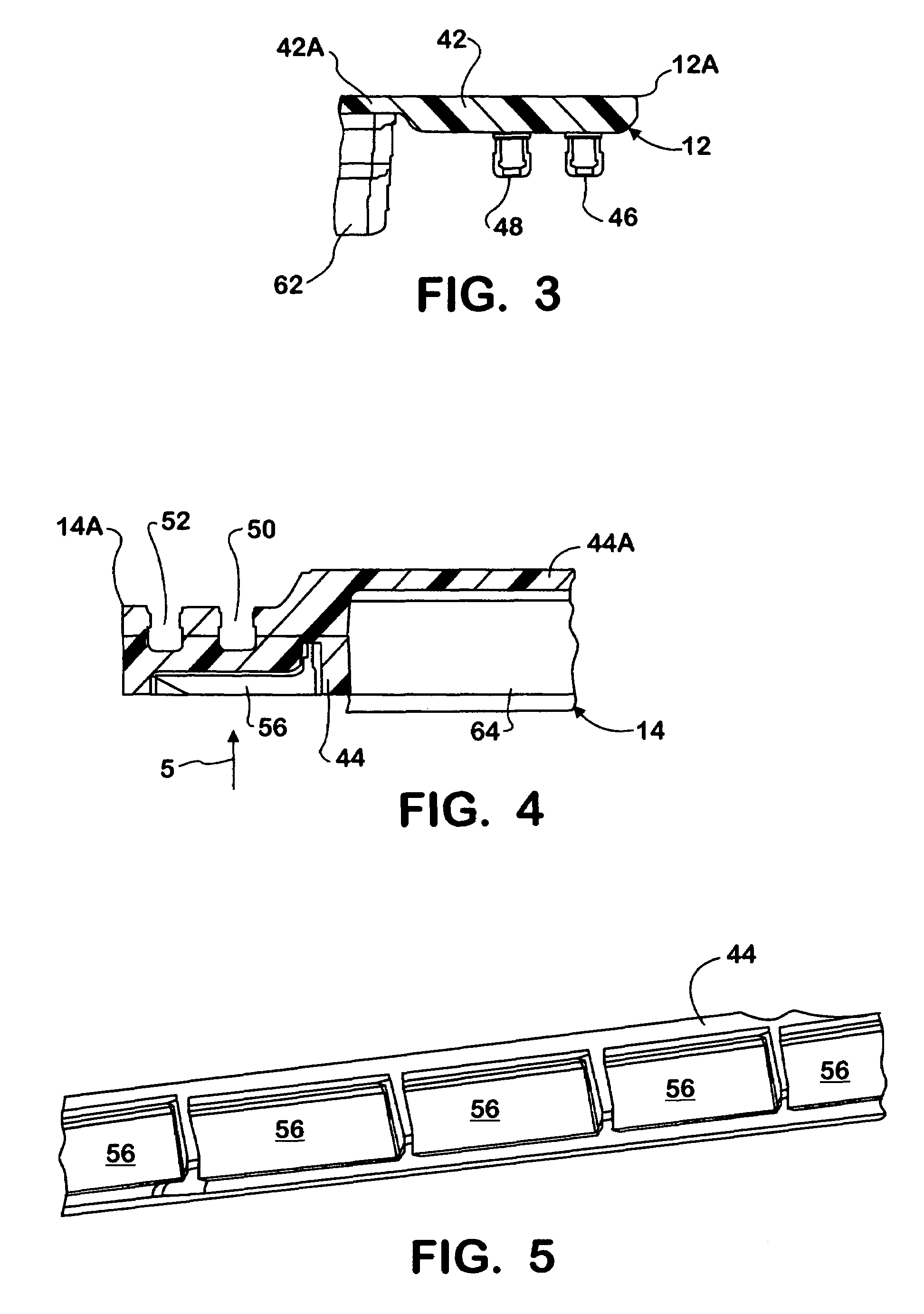
A mobile vehicle has an interior occupant compartment, commonly called a cab when the vehicle is a truck, that has a floor (60) covered by respective floor coverings (12, 14) that have top surfaces opposite the floor. The coverings connect to each other along a joint (16) cooperatively defined by respective over- and under-lapping margins (42, 44) of the respective coverings. One of the margins (44) has two open receptacles (50, 52), and the other (42) has formations (46, 48) each fitted respectively in a respective open receptacle so as to locate the respective top surfaces of the coverings substantially flush with each other and in substantial mutual abutment along the joint. An expanse 42A, 44A that forms at least a portion of the respective top surface is disposed beyond and integrally formed with the respective margin. A foam pad (62, 64) underlies each expanse.

Description

FIELD OF THE INVENTION[0001]This invention relates to a floor covering system of a mobile vehicle, such as a large truck.BACKGROUND OF THE INVENTION[0002]The occupant compartments of motor vehicles, such as cars and trucks, typically have some type of floor covering that is secured in place on the floor. In cars the covering is often a carpeted fabric. In trucks, especially commercial ones, coverings other than carpeted ones are used, rubber or synthetic coverings being common examples.[0003]In some trucks separate smaller floor coverings, rather than a single large floor covering, are used. Functional and / or appearance considerations may call for the use of one or more parts to create a joint along edges where the separate coverings meet. For example, a prior joining technique known to the inventors involves the use of an extruded metal strip that is placed over the margins of the meeting edges, closing any gap between them in the process, and securing the extrusion to the floor by...

Claims


Application Information

Patent Timeline
Patent Type & Authority Patents(United States)
IPC IPC(8): B62D27/00
CPCB60N3/046B60R13/083B60R13/013
Inventor HOFFMAN, MATTHEW A.KITTELSON, ROBERT C.HUG, ROBERT L.
Owner NAVISTAR CANADA
Learn More