Method, imaging device and camera for producing composite image from merged image signals

a composite image and image signal technology, applied in the field of image composition, can solve the problems of unnatural images at this junction, increase the risk of letting them get away a shutter chance of the next photographing scene, and achieve the effect of low cos

Inactive Publication Date: 2010-01-19
FUJIFILM CORP
View PDF9 Cites 13 Cited by
  • Summary
  • Abstract
  • Description
  • Claims
  • Application Information

AI Technical Summary

Benefits of technology

[0017]The object of the invention is to realize an image composition method which yields a composition gamma characteristic of providing smoothness in a connection between a high-sensitivity image signal and a low-sensitivity image signal even when a sensitivity ratio has changed, to thus prevent an image from becoming unnatural. The invention also provides an image composition method, a solid-state imaging device, and a digital camera, which can cope with various photographing scenes by means of a comparatively simple processing circuit.
[0041]By means of this configuration, the circuit scale of the digital camera can be made smaller, thereby enabling photographing of a high-quality image of a subject at low cost.

Problems solved by technology

When signal composition to which the related-art technique of JP-A-2002-135787 has been applied is performed at such a time, the composite signal G becomes deficient in smoothness at a junction between the high-sensitivity image signal Hand the low-sensitivity image signal L, thereby causing a problem of an image becoming unnatural at this junction.
Even when a plurality of gamma characteristics have been prepared beforehand, rewriting of signal composition table data to be performed by the digital camera when a certain photographing scene has been captured involves consumption of much time, thereby raising a problem of an increase in the risk of letting it get away a shutter chance of the next photographing scene.

Method used


Image

  • Method, imaging device and camera for producing composite image from merged image signals
  • Method, imaging device and camera for producing composite image from merged image signals
  • Method, imaging device and camera for producing composite image from merged image signals

Examples


first embodiment

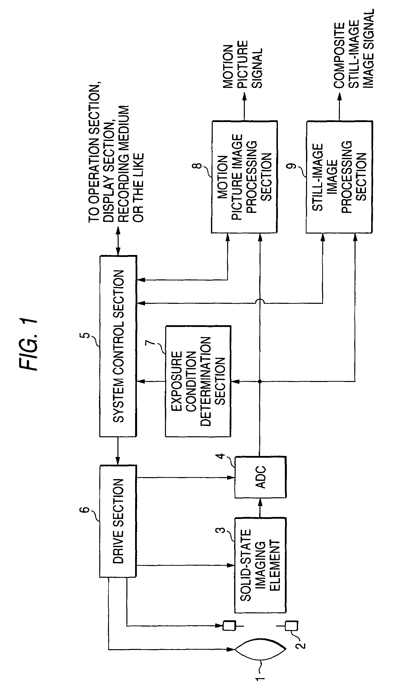
[0052]FIG. 1 is a block diagram of a digital camera according to a first embodiment of the invention. The digital camera is a digital still camera, but the present invention can also be applied to a digital camera of another type, such as a digital video camera.

[0053]In FIG. 1, the digital camera according to the embodiment comprises an optical system 1 such as a lens; a mechanical shutter 2 disposed behind the optical system 1; a solid-state imaging element 3, such as a CCD or CMOS, for converting, into an electrical signal, an optical image of a subject formed by the optical system 1; an analog-to-digital conversion circuit (ADC) 4 for converting an analog image pickup signal output from the solid-state imaging element 3 into a digital signal; a system control section 5 for controlling the entirety of the digital camera in a centralized manner; a drive section 6 for driving and controlling the optical system 1, the mechanical shutter 2, the solid state imaging element 3, and the A...

second embodiment

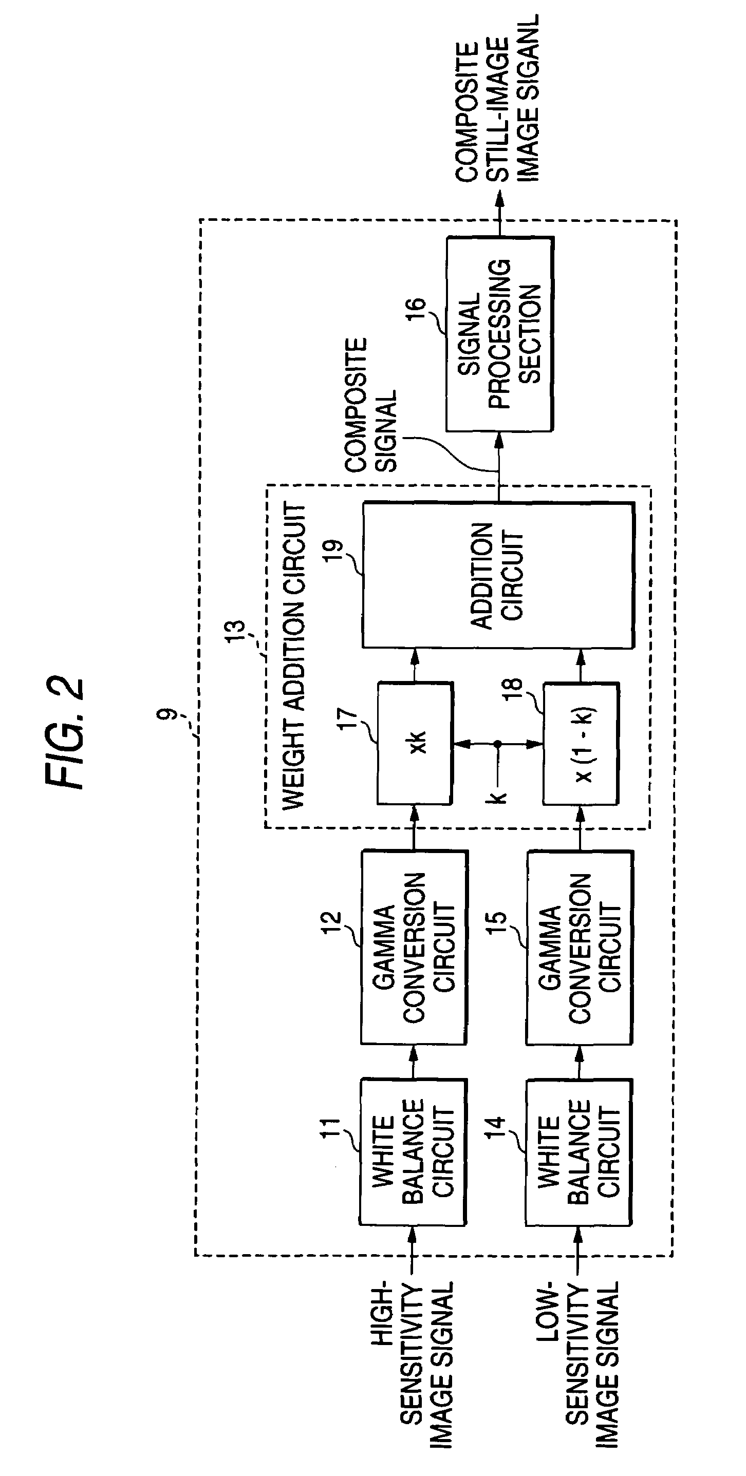
[0079]FIG. 7 is a detailed block diagram of the image processing section 9 of the digital camera according to a second embodiment of the present invention. The entire digital camera is identical in configuration with the digital camera of the first embodiment shown in FIG. 1.

[0080]The present embodiment differs from the first embodiment in that a weight addition circuit 21 for enhancing a signal-to-noise ratio of the low-sensitivity image signal is inserted into a stage subsequent to the white balance circuit 14, which subjects the low-sensitivity image signal to white balance correction, and in that an output from the weight addition circuit is input to the gamma conversion circuit 15. In other respects, the present embodiment is identical with the first embodiment.

[0081]The weight addition circuit 21 receives inputs; that is, a high-sensitivity image signal output from the white balance circuit 11; a low-sensitivity image signal output from the white balance circuit 14; and the se...

third embodiment

[0084]FIG. 8 is a detailed block diagram of the image processing section 9 of the digital camera according to a third embodiment of the present invention. The entire digital camera of the third embodiment is identical in configuration with the digital camera of the first embodiment shown in FIG. 1 and that of the second embodiment.

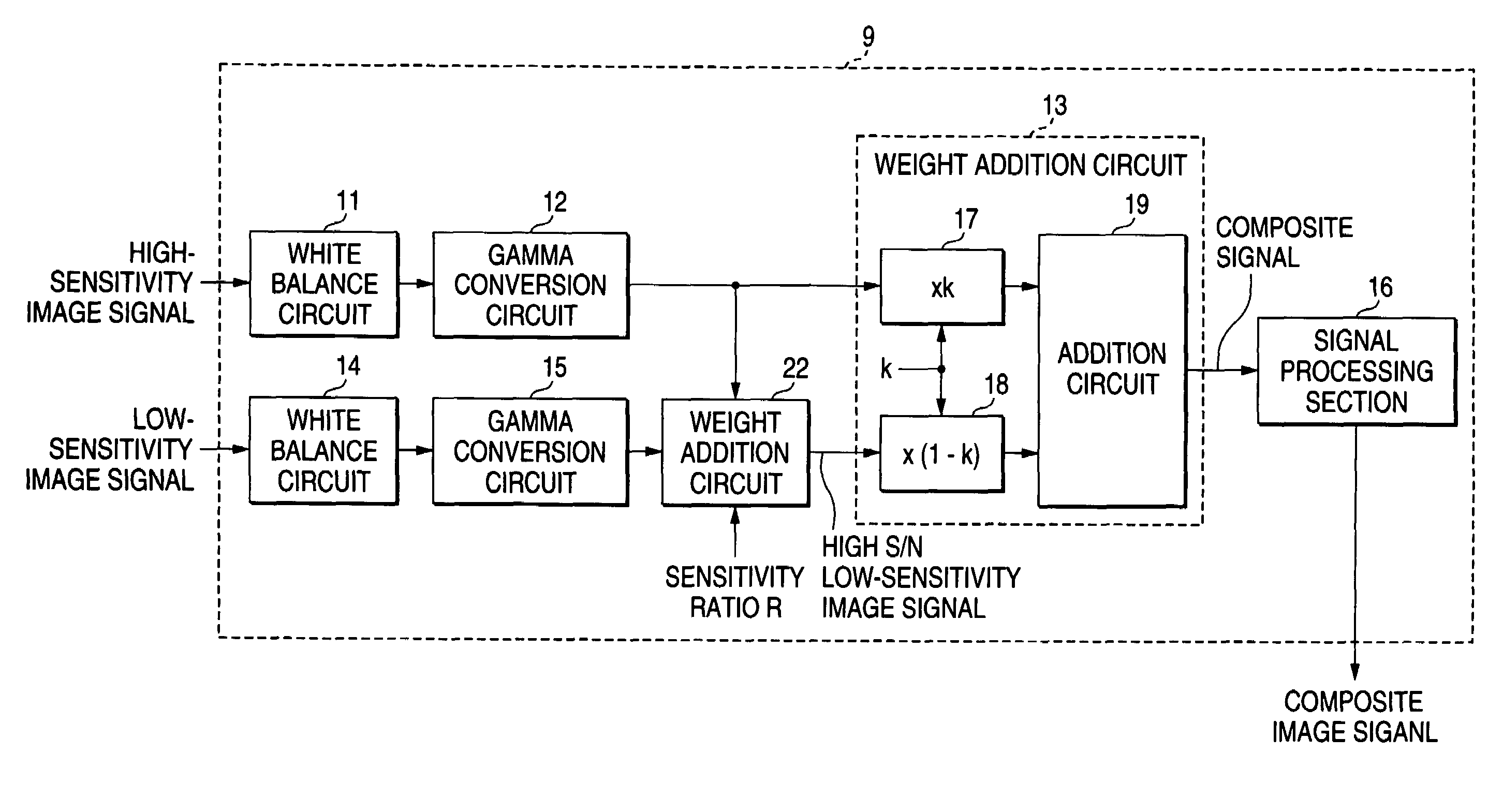
[0085]The present embodiment differs from the second embodiment in that a weight addition circuit 22 is provided in a stage subsequent to the gamma conversion circuit 15, in contrast with the second embodiment in which the weight addition circuit 21 is disposed at the stage prior to the gamma conversion circuit 15. In other respects, the present embodiment is identical with the second embodiment.

[0086]In the second embodiment, the linear value of the low-sensitivity image signal is subjected to enhancement of the signal-to-noise ratio of the low-sensitivity image signal. In contrast, in the present embodiment the low-sensitivity image signal having undergo...


PUM


Abstract

An image composition method comprises: subjecting a first high-sensitivity image signal generated based on high-sensitivity image outputs from corresponding ones of a plurality of pixel positions in a solid-state imaging element that has imaged a subject, to a first nonlinear conversion, so as to prepare a second high-sensitivity image signal; subjecting a first low-sensitivity image signal generated based on low-sensitivity image outputs from corresponding ones of the plurality of pixel positions, to a second nonlinear conversion, so as to prepare a second low-sensitivity image signal; and subjecting the second high-sensitivity image signal and the second low-sensitivity image signal to weight adding at every common pixel position, over the entire range of an incident light exposure level exhibited by each incident light that entered to each of the plurality of pixel positions, so as to produce a composed image signal of the subject.

Description

[0001]This Non-provisional application claims priority under 35 U.S.C. § 119(a) on Patent Application No(s). 2003-283964 filed in Japan on Jul. 31, 2003, the entire contents of which are hereby incorporated by reference.BACKGROUND OF THE INVENTION[0002]1. Field of the Invention[0003]The present invention relates to an image composition method or the like for producing an image signal having a wide dynamic range by merging together a high-sensitivity image signal and a low-sensitivity image signal, which have been obtained by means of photographing a subject, and more particularly, to an image composition method, a solid-state imaging device, and a digital camera, which prevent a composite image from becoming unnatural in the vicinity of a saturation point of the high-sensitivity image signal.[0004]2. Description of the Related Art[0005]An image photographed by a solid-state imaging device using a solid-state imaging element typified by a CCD image sensor or a CMOS image sensor has a...

Claims


Application Information

Patent Timeline
Patent Type & Authority Patents(United States)
IPC IPC(8): H04N5/225H04N5/262H04N5/235H04N101/00
CPCH04N5/235H04N23/70
Inventor SUZUKI, NOBUO
Owner FUJIFILM CORP
Why Eureka
Try Eureka