Oil collector

An oil collector and fuel injector technology, which is applied in the field of oil collectors, can solve the problems of complex measurement accuracy, unfavorable promotion and application, high cost, etc., and achieves the effects of simple processing circuit, strong anti-interference ability and reliable operation.

Inactive Publication Date: 2007-07-11
HENAN UNIV OF SCI & TECH
View PDF4 Cites 0 Cited by
  • Summary
  • Abstract
  • Description
  • Claims
  • Application Information

AI Technical Summary

Problems solved by technology

At present, the common pressure sensors on the market have various forms such as piezoelectric sensors and piezoresistive sensors. Due to the consideration of measurement accuracy, the structure is relatively complicated, and corresponding amplification or conditioning circuits must be configured and passed through A / D. After conversion, it can be transmitted to the microcomputer for processing. If these sensors are directly used as the test signal source on the fuel injection pump test bench, it will not only have a complex structure, a large volume, but also be expensive, which is not conducive to popularization and application.

Method used


Image

  • Oil collector
  • Oil collector

Examples


Embodiment Construction

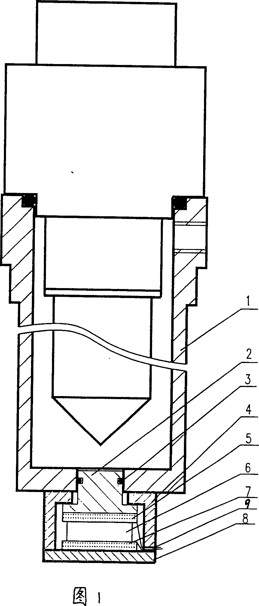
[0008] As shown in Figure 1, a fuel injection sensor is installed on the fuel collector 1 of the present invention, wherein the fuel injection sensor is a piezoelectric fuel injection sensor, and the piezoelectric fuel injection sensor includes an induction column 2 made of an insulating material, The induction column 2 is inserted into the socket provided at the bottom of the oil collector. A sealing ring 3 is installed between the induction column 2 and the socket. Sheet 7 and pressure plate 8, the above-mentioned components are packaged in the sensor housing 4, the upper conductive sheet 5 is in contact with the pressure plate 8 through high-impedance insulated wires, and the lower conductive sheet 7 is in contact with the pressure plate 8, and the wires are connected from the gap 9 on the metal sensor housing 4 respectively. lead out. When the injector injects oil, the oil pressure in the oil collector 1 rises, and the induction column 2 transmits this pressure to the piez...


PUM


Abstract

This is oil collector used of the testing platform of injection pump. On this oil collector is installed oil injection sensor. This sensor is not only to ensure every oil cylinder is whether not inject oil but also can to survey every oil cylinder injective moment (or phase angle), then to calculate dynamic injective phase angle. As only to differentiate in the collector is whether not injection, so the sensor's linear degree can be lower, and its construction is simple. The output signals of this sensor are switched signals using to show the injection or not injection, so its resist disturbed ability is strong.

Description

technical field [0001] The invention relates to an oil collector which can judge whether there is oil sprayed in according to the oil pressure fluctuation range in the container. Background technique [0002] The oil pressure in the oil collector is measured using a specially designed pressure sensor. At present, the common pressure sensors on the market have various forms such as piezoelectric sensors and piezoresistive sensors. Due to the consideration of measurement accuracy, the structure is relatively complicated, and corresponding amplification or conditioning circuits must be configured and passed through A / D. After the conversion, it can be transmitted to the microcomputer for processing. If these sensors are directly used as the test signal source on the fuel injection pump test bench, it will not only have a complex structure, a large volume, but also a high cost, which is not conducive to popularization and application. Contents of the invention [0003] In vie...

Claims


Application Information

Patent Timeline
Patent Type & Authority Patents(China)
IPC IPC(8): G01L7/00G01L23/00
Inventor 刘建新邓本都赵致和朱邦太宗永平李勋李民杜慧勇
Owner HENAN UNIV OF SCI & TECH
Why Eureka
Try Eureka