
Thin-film magnetic head with heating element and heatsink

a heating element and heatsink technology, applied in the field of thin-film magnetic heads with heating elements and heatsinks, can solve the problems of excessive heating physical damage or crash the magnetic disk, and increase the temperature of the heater itself, so as to improve the protruding efficiency of the magnetic head element, improve the reliability of the heating operation, and stabilize the read output

Active Publication Date: 2010-01-19
TDK CORPARATION +1
View PDF18 Cites 22 Cited by
  • Summary
  • Abstract
  • Description
  • Claims
  • Application Information

AI Technical Summary

Benefits of technology

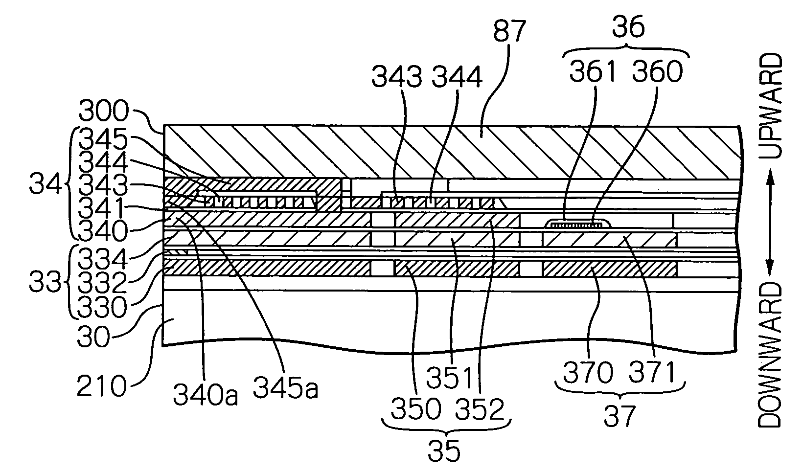
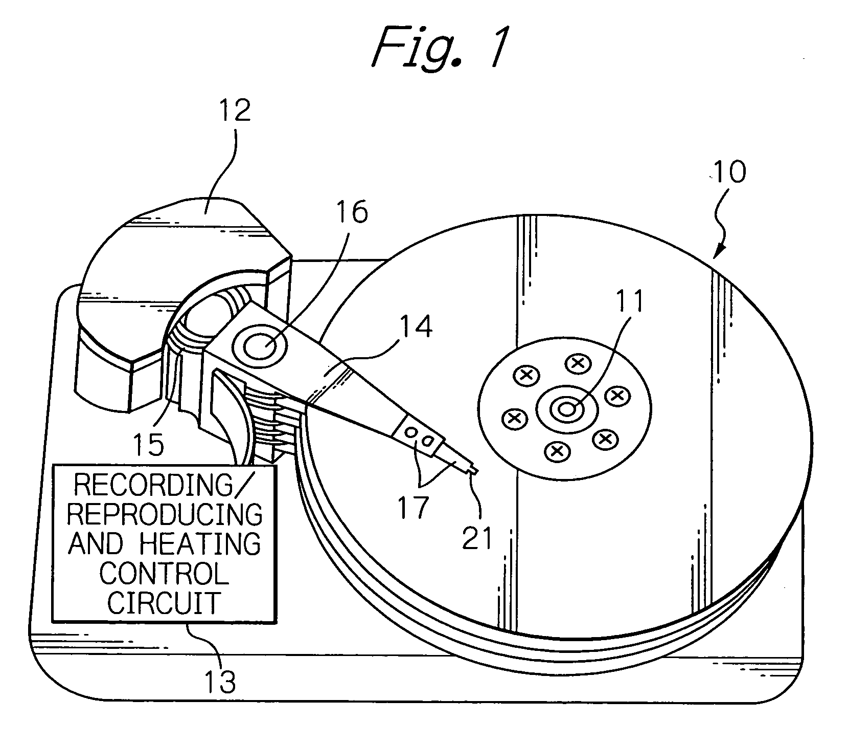
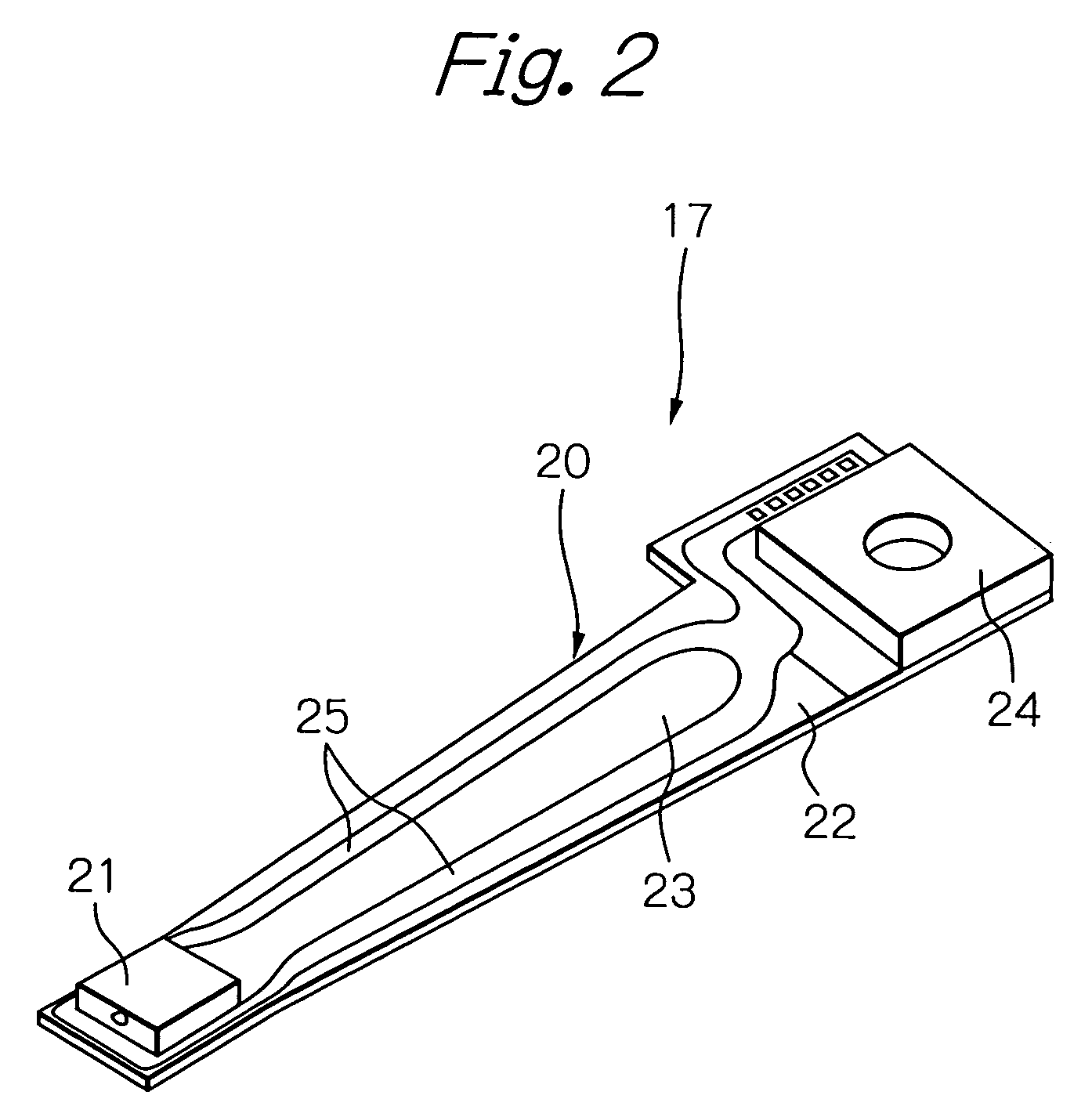
The present invention provides a thin-film magnetic head with improved protrusion efficiency of the magnetic head element due to the heat generated by the heating element, while preventing excess increase in temperature that can affect the read output of the MR read head element. The thin-film magnetic head includes a heatsink element adjacent to the heating element to receive a part of the heat generated during operation. The heatsink element is physically separate from the magnetic head element, which prevents the heat from affecting the read output of the MR read head element. The thin-film magnetic head is suitable for use in a magnetic disk drive apparatus.

Problems solved by technology

The contact by the protrusion has a possibility of making trouble (thermal asperity) such as an occurrence of abnormal signals, and further has a risk of causing physical damage or crash of the magnetic head element and the magnetic disk.
As a result, the whole amount of protrusion of the head end surface per applied power becomes larger.
However, the miniaturization of the heater is likely to cause the temperature of the heater itself to be increased excessively.
Therefore, the heater is needed to have a high-precision in position and size, however, the excess increase in temperature has a possibility to cause the heater to be deformed, and what is more, to be destroyed due to breaking and so on.
Therefore, in the case of the excess increase in temperature, not only the required degree of precision, but also the heating operation itself is not assured.
However, a problem occurs that the heat generated from the heater is likely to degrade the reliability of the MR read head element.
The significant increase in temperature is likely to cause deterioration in the reliability, and what is more, the output stability of the MR read head element.
Especially, a giant magnetoresistive (GMR) read head element, which is recently well-used, has a comparatively high risk to make such a problem.

Method used


Image

  • Thin-film magnetic head with heating element and heatsink
  • Thin-film magnetic head with heating element and heatsink
  • Thin-film magnetic head with heating element and heatsink

Examples


embodiment 1

A Structure of an Embodiment 1

[0127]FIG. 12a shows a cross-sectional view illustrating a structure of a main part in a thin-film magnetic head of an embodiment 1 according to the present invention, and FIG. 12b shows a plain view explaining the size and position of a heater heatsink element in the thin-film magnetic head.

[0128]According to FIGS. 12a, the structure and configuration of a heating element 1200, a heater heatsink element (first heatsink element) 1201 and a coil heatsink element (second heatsink element) 1202 are almost the same as those of the embodiment shown in FIG. 4a. The heater heatsink element 1201 includes first and second heater heatsink layers as main layers. According to FIG. 12b, the heater heatsink element 1201 has a rectangular shape and a size of WHS1=90 μm and LHS1=30 μm, where the WHS1 is a length of the shape in the track-width direction and the LHS1 is a length of the shape in the direction perpendicular to the ABS (head end surface 300). The spacing G...

embodiments 2 and 3

[0141]Hereinafter, the results of simulating the amount of temperature increase and the amount of protrusion in various structures of the heater heatsink element will be explained.

[0142]Table 2 illustrates the results of the simulations of the temperature increase per power and the amount of protrusion per temperature in embodiments 2 and 3. The results of the embodiment 1 are also described in the table to facilitate comparisons of values. Here, the heater heatsink element of the embodiment 2 has a monolayered structure as shown in FIG. 5c, and the heater heatsink element of the embodiment 3 has a mainly three-layered structure of the first, second and third heater heatsink layers as shown in FIG. 5a. In the simulations, the resistance value of the heating element was 100 ohm, and the applied power to the heating element was 100 mW. The amount of protrusion was determined as a protrusion value at a read gap between the upper and lower shield layers in the head end surface. Further,...

embodiments 1 and 4 to 7

[0147]Hereinafter, the results of simulating the amount of temperature increase and the amount of protrusion in the thin film magnetic heads with heater heatsink elements of various sizes (areas) will be explained.

[0148]The embodiments 4 to 7 have structures shown in FIGS. 12a and 12b as the embodiment 1, and have heater heatsink elements with sizes different from each other.

[0149]In the embodiments 4, 5 (and 1), the WHS1 is the same value of 90 μm, however the LHS1 is 11, 16 (and 30) μm respectively. In the embodiments 6, 7 (and 1), the LHS1 is the same value of 30 μm, however the WHS1 is 30, 50 (and 90) μm respectively. Further, in the embodiments 4 to 7 (and 1), the G2=5 μm and the LMP=25 μm.

[0150]Table 3 illustrates the results of the simulations of the temperature increase per power and the amount of protrusion per temperature in the embodiments 1 and 4 to 7. In the table, the results of the embodiment 1 are also illustrated, arranged twice respectively with the embodiments 4 a...


PUM

PropertyMeasurementUnit
thicknessaaaaaaaaaa
thicknessaaaaaaaaaa
thicknessaaaaaaaaaa

Abstract

A thin-film magnetic head that has an improved protrusion efficiency under the condition of not only assuring the reliability of the-heating operation, but also stabilizing the read output is provided. The head comprises: a magnetic head element for writing and / or reading data signals; a heating element for generating heat at least during operations of the magnetic head element; and a first heatsink element provided adjacent to the heating element for receiving a part of the heat generated from the heating element, the first heatsink element being a distance from the magnetic head element.

Description

PRIORITY CLAIM[0001]This application claims priority from Japanese patent application No. 2005-188017, filed on Jun. 28, 2005, which is incorporated herein by reference.BACKGROUND OF THE INVENTION[0002]1. Field of the Invention[0003]The present invention relates to a thin-film magnetic head with a heating element and a heatsink, a head gimbal assembly (HGA) with the thin-film magnetic head and a magnetic disk drive apparatus with the HGA.[0004]2. Description of the Related Art[0005]In a magnetic disk drive apparatus, when writing or reading signals, a thin-film magnetic head (slider) hydrodynamically flies with a predetermined spacing (flying height) on a rotating magnetic disk. While flying on the magnetic disk, the thin-film magnetic head writes signals to the magnetic disk using magnetic fields generated from an inductive write head element, and reads signals by sensing magnetic fields corresponding to the signals from the magnetic disk with the use of an magnetoresistive (MR) ef...

Claims


Application Information

Patent Timeline
Patent Type & Authority Patents(United States)
IPC IPC(8): G11B5/127
CPCG11B5/3133G11B5/4826G11B5/6005G11B5/6064G11B2005/0005
Inventor OTA, NORIKAZUKURIHARA, KATSUKIHIRABAYASHI, HIRAKUOIKE, TAROMATSUKUMA, HIROKI
Owner TDK CORPARATION
Learn More