

Change detection equipment and method of image recognition
a technology of change detection and equipment, applied in the field of change detection equipment and image recognition, can solve the problems of prior art technique, inability to detect changes when appropriate maps, and inability to determine changes using a plurality of properties including a geometric property, image property,
- Summary
- Abstract
- Description
- Claims
- Application Information
AI Technical Summary
Benefits of technology
Problems solved by technology
Method used
Image

Examples
Embodiment Construction
[0019]In the following, embodiments of the present invention will be described with reference to the accompanying drawings. It should be noted that the embodiments described below may be implemented by a program read and executed by a computer, in hardware, or by cooperative processing of software and hardware.
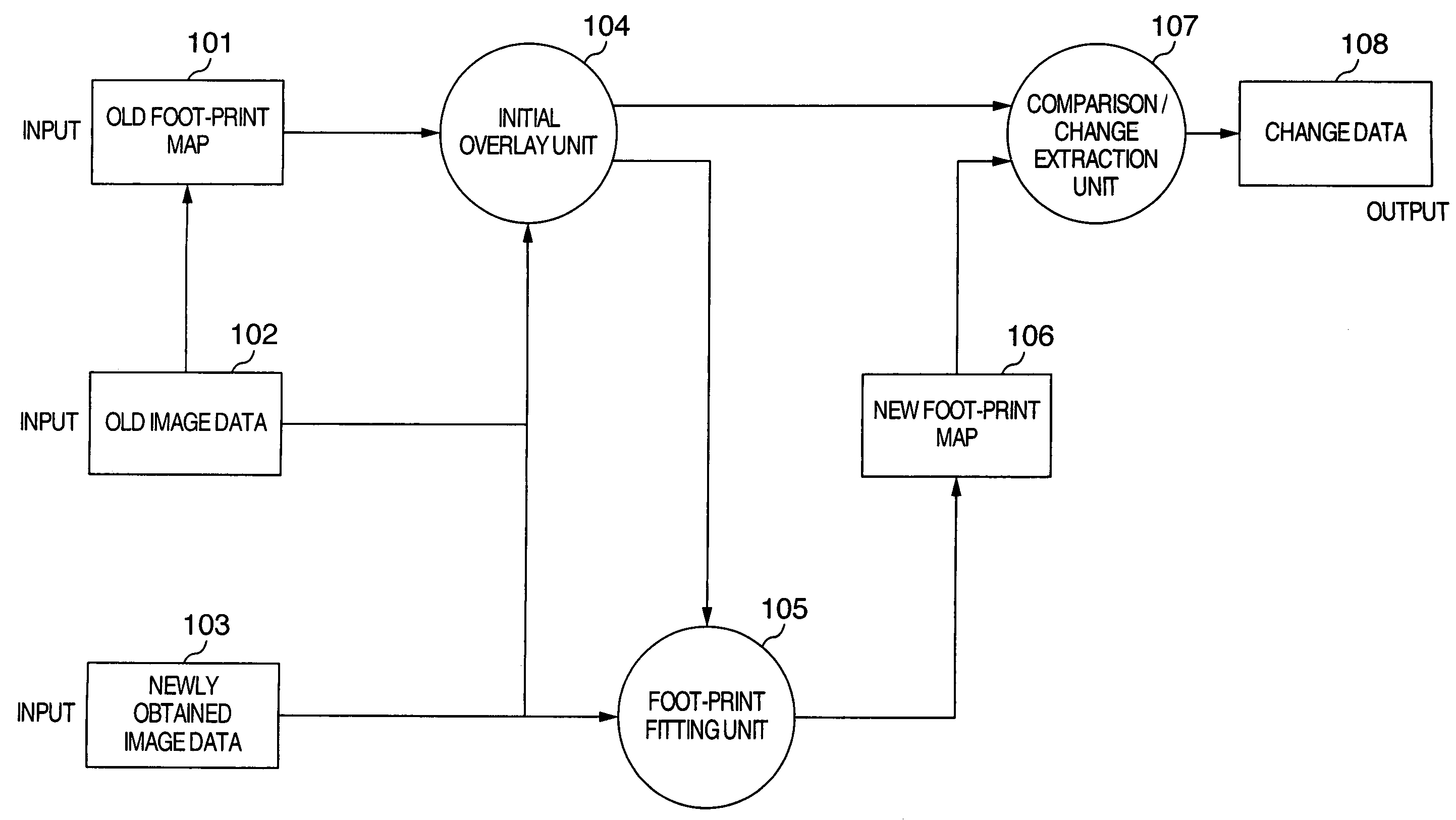
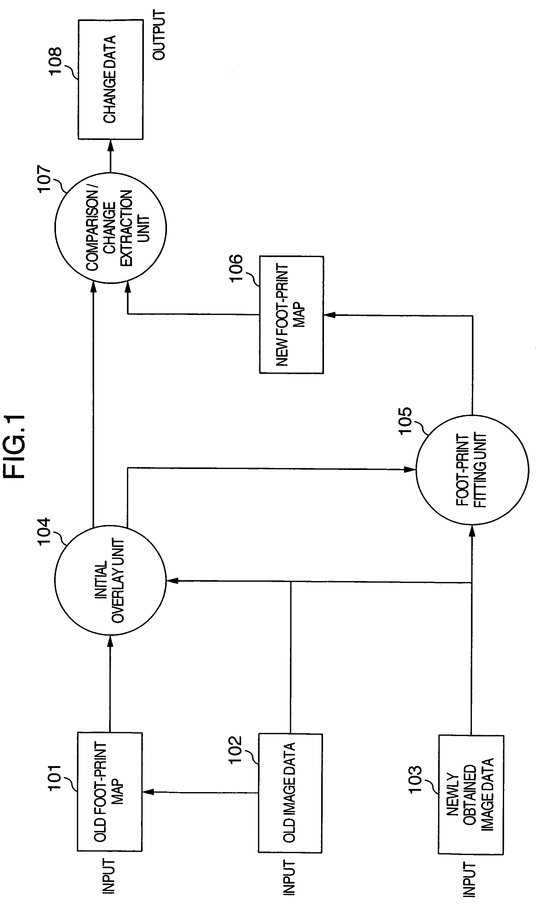
[0020]FIG. 1 is a functional block diagram illustrating the configuration of a processing apparatus for object change detection processing based on matching of new and old images according to one embodiment of the present invention. The processing apparatus receives old image data 102, an old foot-print map 101 created from an old image, new image data 103, and the like. The processing apparatus comprises an initial overlay unit 101 for initially aligning a foot-print to a newly obtained image; a foot-print fitting unit 105 for searching for an image area in the newly obtained image of an object corresponding to the old foot-print map; and a comparison and change extraction un...
PUM
 Abstract
Description
Claims
Application Information