System and method for controlling communication between a host computer and communication devices associated with remote devices in an automated monitoring system

a communication system and host computer technology, applied in the direction of electrical programme control, program control, instruments, etc., can solve the problems of increasing the cost of developing the local sensor-actuator infrastructure necessary to interconnect the various devices, the added cost of connecting functional sensors and actuators with the local controller, and the added cost of adding additional costs, etc., to simplify the communication device, and reduce the cost and complexity

Inactive Publication Date: 2010-01-19
SIPCO
View PDF630 Cites 287 Cited by
  • Summary
  • Abstract
  • Description
  • Claims
  • Application Information

AI Technical Summary

Benefits of technology

[0010]Thus, the site controller according to the present invention minimizes cost and complexity by providing a site controller to maintain the bulk of the data needed by the user and by providing simplified and inexpensive communication devices to collect and communicate th

Problems solved by technology

One problem with expanding the use of control systems technology to distributed systems is the cost associated with developing the local sensor-actuator infrastructure necessary to interconnect the various devices.
Not only is there expense associated with developing and installing appropr

Method used


Image

  • System and method for controlling communication between a host computer and communication devices associated with remote devices in an automated monitoring system
  • System and method for controlling communication between a host computer and communication devices associated with remote devices in an automated monitoring system
  • System and method for controlling communication between a host computer and communication devices associated with remote devices in an automated monitoring system

Examples


Embodiment Construction

[0019]Having summarized the invention above, reference is now made in detail to the description of the invention as illustrated in the drawings. While the invention will be described in connection with these drawings, there is no intent to limit it to the embodiment or embodiments disclosed therein. On the contrary, the intent is to cover all alternatives, modifications and equivalents included within the spirit and scope of the invention as defined by the appended claims.

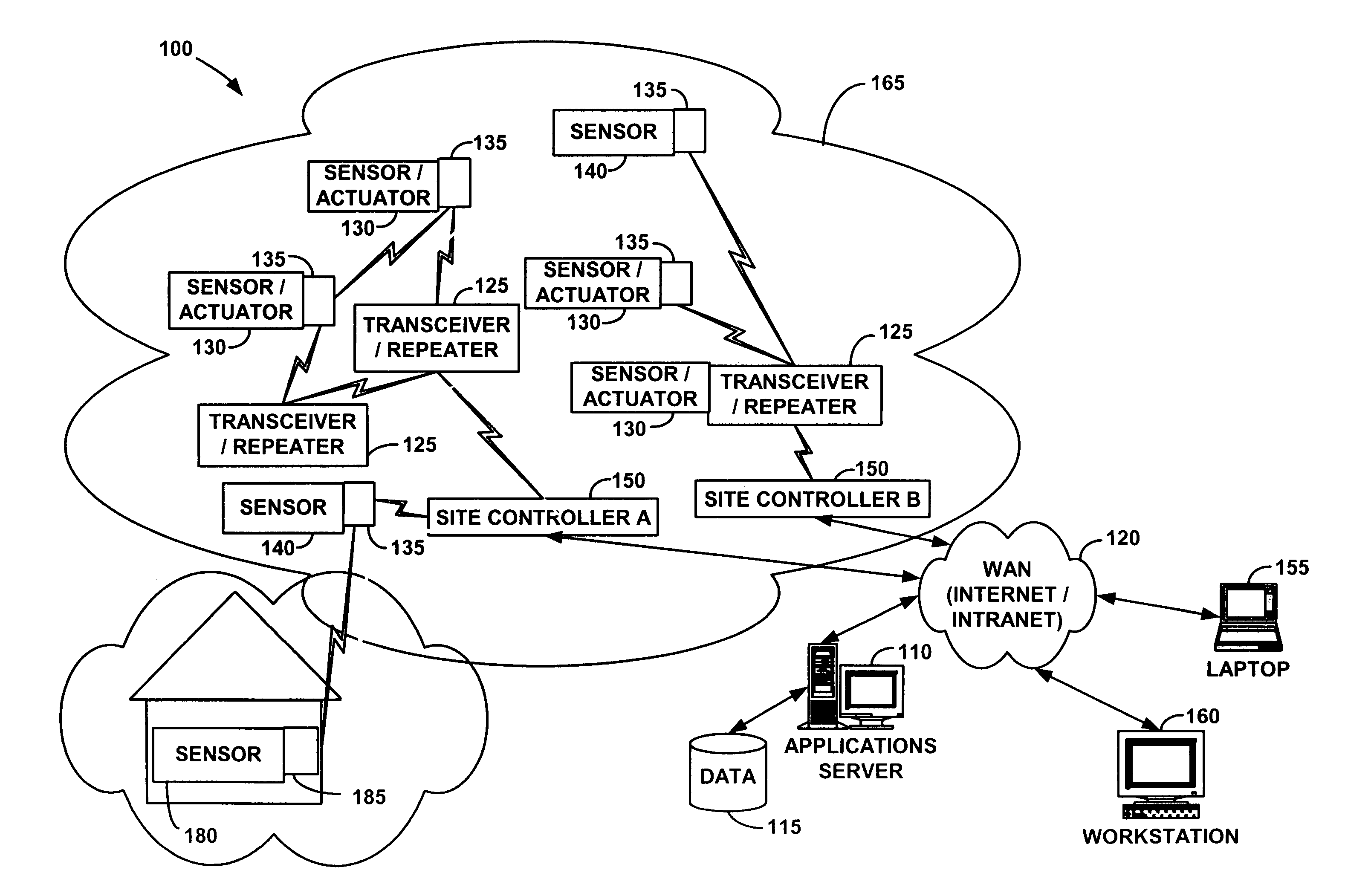
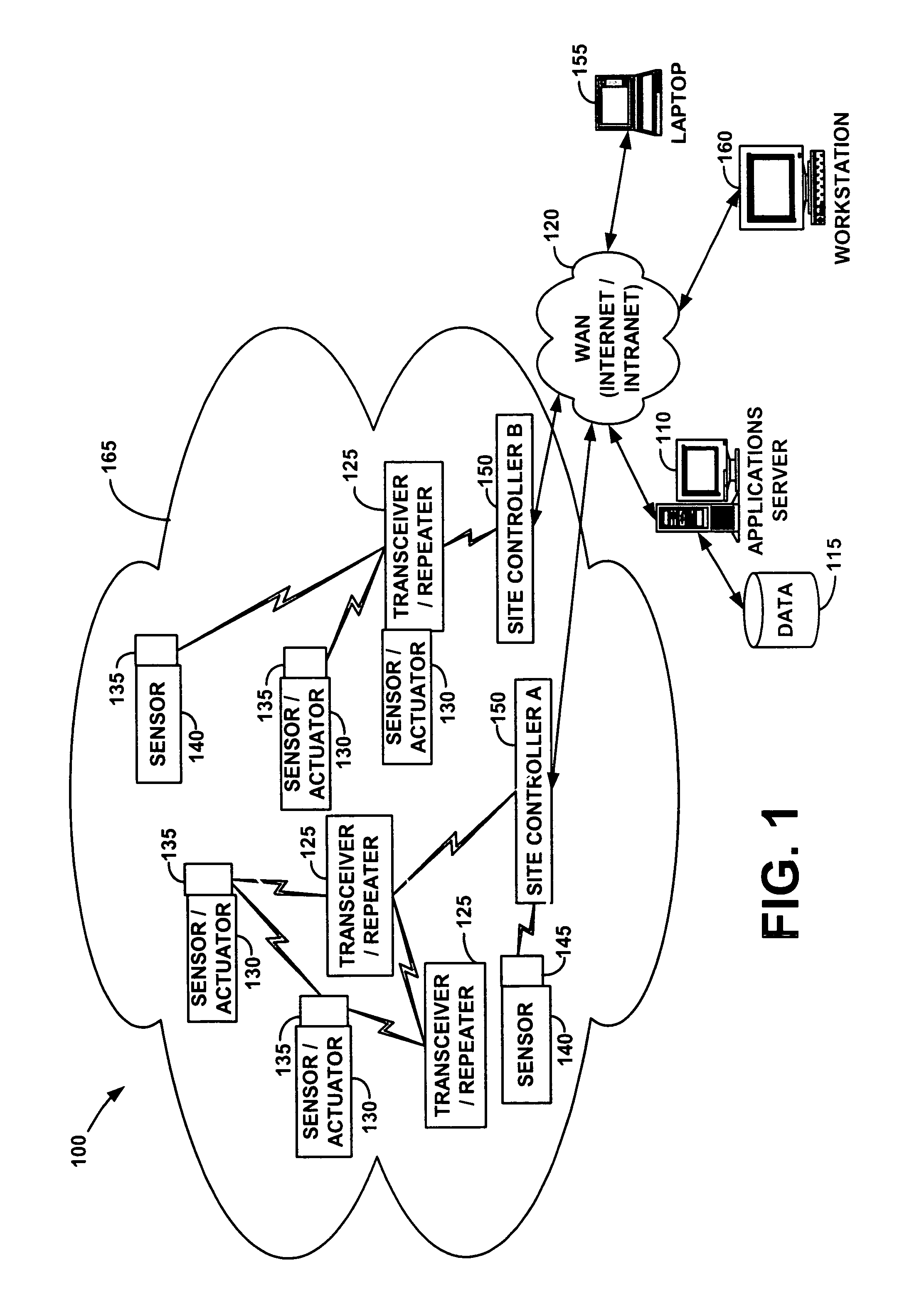
[0020]FIG. 1 is a block diagram illustrating one of a number of possible embodiments of an automated monitoring system 100 according to the present invention. Automated monitoring system 100 may comprise one or more applications servers 110, a database 115, a wide area network (WAN) 120, transceivers / repeaters 125, sensor / actuators 130, transceivers 135, sensors 140, transmitters 145, and at least one site controller 150. Each of the sensor / actuators 130 and sensors 140 is integrated with a suitably configured wire...


PUM


Abstract

A site controller adapted to be used in an automated monitoring system for monitoring and controlling a plurality of remote devices via a host computer connected to a first communication network is provided. The site controller is configured for controlling communication with the host computer and a plurality of communication devices that define a second communication network associated with the plurality of remote devices. Briefly described, in one embodiment, the site controller comprises a transceiver configured to communicate with the plurality of communication devices via the second communication network; a network interface device configured to communicate with the host computer via the first communication network; and logic configured to: manage communication with each of the plurality of communication devices, via a first communication protocol, based on one or more communication paths for each of the plurality of communication devices, each communication path comprising one or more communication devices involved in the communication link between the transceiver and each of the plurality of communication devices; and manage communication with the host computer via a second communication protocol.

Description

CROSS-REFERENCE TO RELATED APPLICATIONS[0001]This application is a continuation-in-part of the following U.S. utility patent applications: U.S. patent application Ser. No. 09 / 271,517, filed Mar. 18, 1999, and entitled, “System For Monitoring Conditions in a Residential Living Community,”, now abandoned; U.S. patent application Ser. No. 09 / 439,059, filed Nov. 12, 1999, and entitled, “System and Method for Monitoring and Controlling Remote Devices”, now U.S. Pat. No. 6,437,692, issued Aug. 20, 2002; U.S. patent application Ser. No. 09 / 812,809, filed Mar. 20, 2001, and entitled, “System and Method for Monitoring the Light Level in a Lighted Area”, now abandoned, which is a continuation-in-part of U.S. patent application Ser. No. 09 / 412,895, filed Oct. 5, 1999, and entitled, “System For Monitoring the Light Level Around and ATM,” now U.S. Pat. No. 6,218,953, issued Apr. 17, 2001. Each of the identified U.S. patent applications is incorporated herein by reference in its entirety. This ap...

Claims


Application Information

Patent Timeline
IPC IPC(8): G06F15/173G01D4/00G05B19/042G05B19/418G08B25/00G08C17/02H04L12/26H04L29/06H04M11/04
CPCG01D4/004G05B19/4185G08B25/007G08B25/009G08C17/02H04L29/06H04L43/00H04M11/04H04W40/00H04L45/00H04L43/0876H04W24/08G05B19/042H04W84/04G05B2219/25198G08C2201/40G08C2201/42G08C2201/51H04L43/10Y02B90/242Y04S20/322H04L69/08H04L9/40Y02B90/20Y04S20/30
Inventor DAVIS, JAMESPETITE, THOMAS D.
Owner SIPCO
Why Eureka
Try Eureka