
Electrically-actuated transfer seat

a technology of electric actuators and transfer seats, which is applied in the direction of transportation items, loading/unloading vehicle arrangment, and refuse collection, etc., can solve the problems of difficult lifting and transferring persons to and from wheelchairs, difficulty in entering or exiting vehicles, and difficulties for semi-ambulatory persons, so as to facilitate secure storage and alleviate potential impact and injury concerns, the effect of facilitating the storage of items

Inactive Publication Date: 2010-01-26
EGAN THOMAS F
View PDF74 Cites 13 Cited by
  • Summary
  • Abstract
  • Description
  • Claims
  • Application Information

AI Technical Summary

Benefits of technology

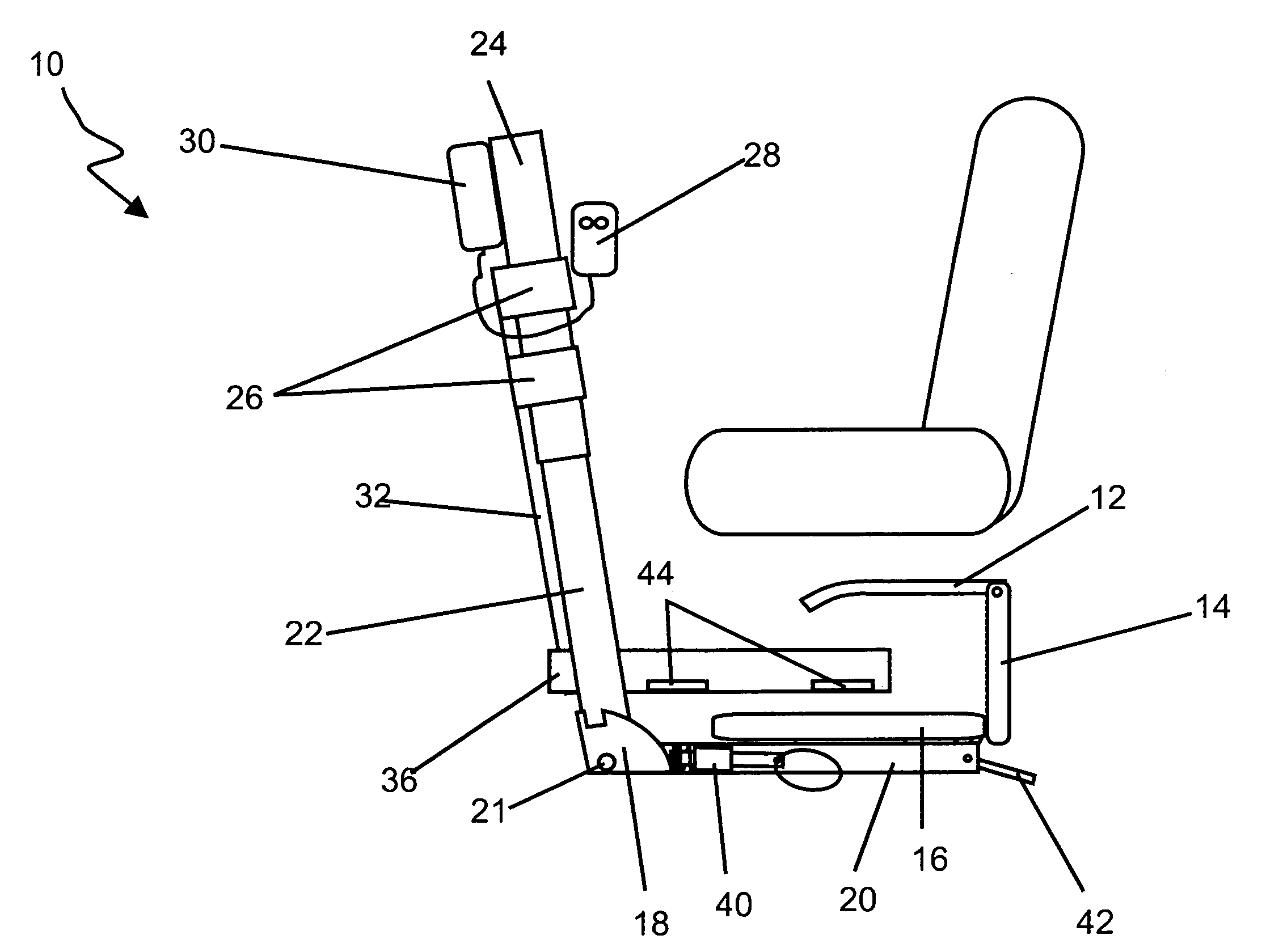
[0009]The present invention may be realized in two or more versions, including a single-fold version and a bi-fold version. The bi-fold version incorporates the aforementioned capability of pivoting about a substantially horizontal axis at the base of the extension arm to a locking position once it has reached a substantially vertical orientation for purposes of easy storage and greater lifting range.
[0011]In accordance with still further aspects of the present invention, the alternatively pivoting horizontal support member can incorporate a cam-style locking mechanism with a spring-loaded locking pin to facilitate secure storage of the horizontal support member and seat assembly when in a substantially vertical stored position. This feature alleviates concerns of potential impact and injury associated with frontal collisions.
[0012]In accordance with still further aspects of the present invention, the seat assembly can alternatively incorporate a lever-operated locking mechanism for purposes of securing the seat in a substantially vertical plane when the horizontal support member and seat assembly are in the upright and locked position. This feature alleviates concerns of potential impact and injury associated with unintended rotation of the seat assembly due to normal vehicle motion or impact.
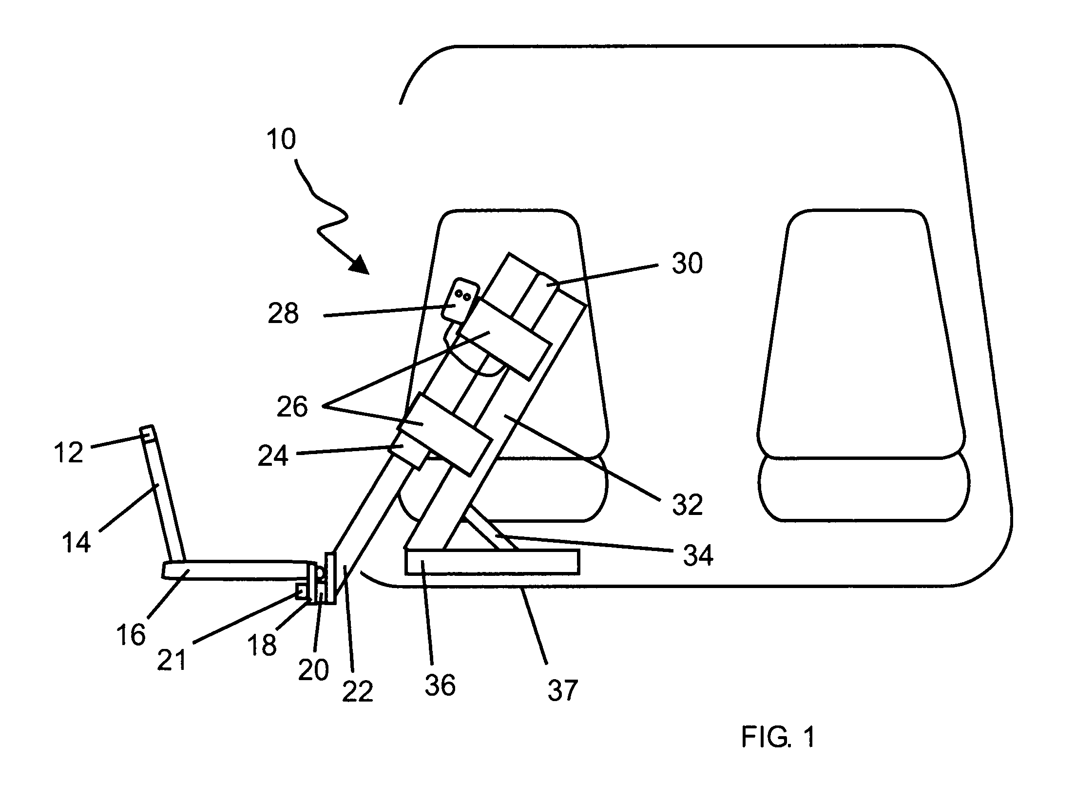
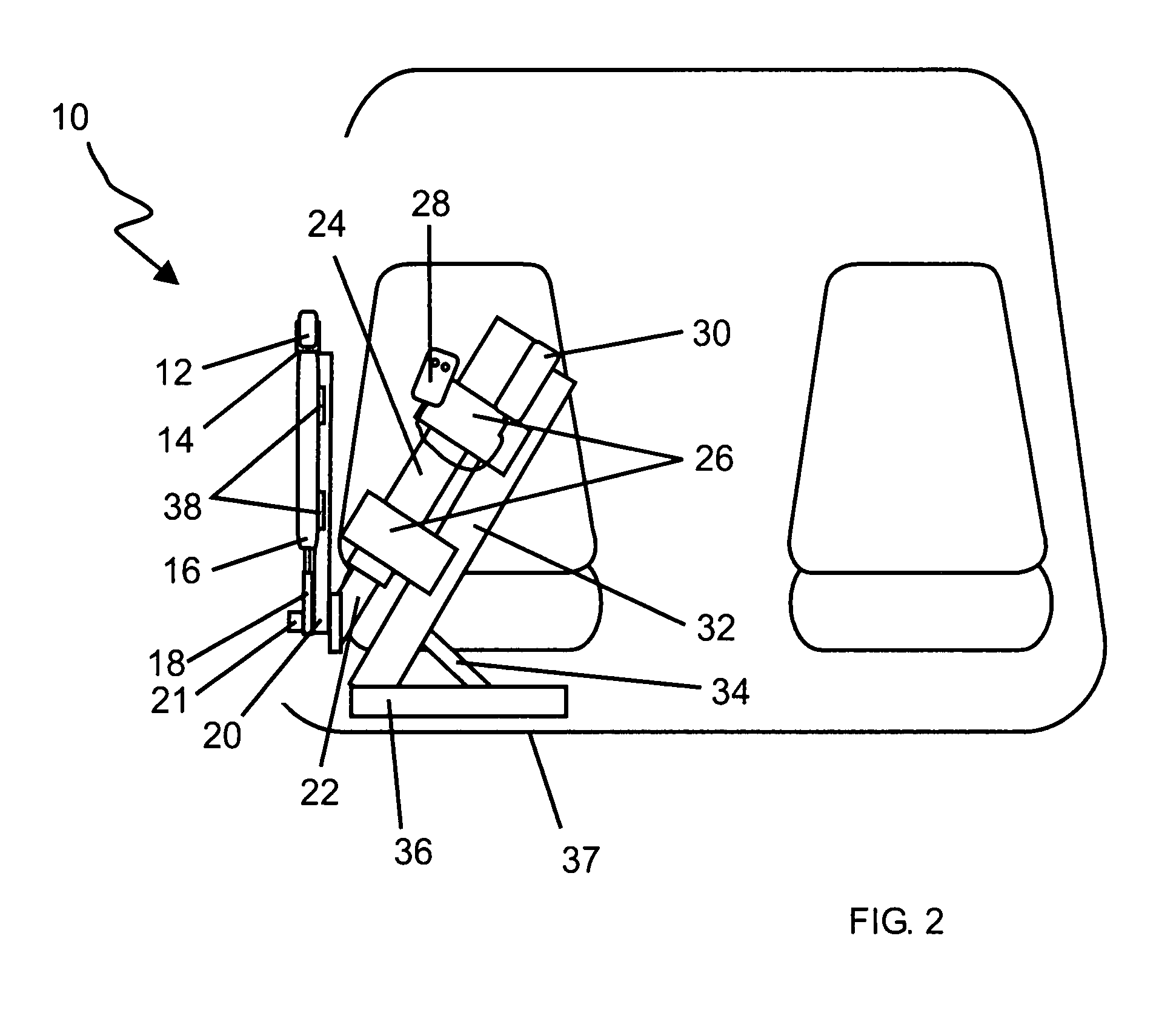
[0014]In accordance with still further aspects of the present invention, the seat lifting and transferring apparatus may alternatively incorporate a first means of support designed to attach to the electric or hydraulic extension arm to the chassis of the vehicle via a support structure having a horizontal support member aligned with the axis of the electric or hydraulic extension arm, and vertical support members aligned with the plane of the vehicle floor board for purposes of affixing the support structure to pre-existing vehicle seat and belt system fasteners. This feature alleviates concerns of compromise to vehicle structural integrity due to drilling, and greatly reduces installation times and vehicle degradation due to the installation of this equipment.

Problems solved by technology

Difficulties are often encountered when a disabled person transfers from one location to another whether independently or assisted.
Particularly in the case of wheelchair-bound persons or persons with severe mobility impairments, it is often quite difficult to lift and transfer persons to and from their wheelchair when entering or exiting a motor vehicle.
Additionally, persons who are semi-ambulatory may have difficulties entering or exiting vehicles which are substantially higher or lower than the level required for comfortable entry or egress.
However, the devices disclosed in these patents, as well as other known devices, have drawbacks in the areas of cost and complexity which could limit the potential mobility of a disabled individual.
For instance, a product called Easy Rizer™, which is presently on the market, requires extensive modifications to the chassis of a vehicle, thus incurring substantial costs and delays in installation times, substantial modifications to the original appearance and esthetics of the vehicle, as well as important safety concerns as to potential compromises of the structural integrity and occupant crash protection.
Additionally, this type of product, due to inherent limitations of its size and design, is applicable only to a limited range of body styles in the van and truck vehicle category.

Method used


Image

  • Electrically-actuated transfer seat
  • Electrically-actuated transfer seat
  • Electrically-actuated transfer seat

Examples


Embodiment Construction

[0036]Referring to FIGS. 1-2, there is shown a lifting and transferring apparatus 10 in accordance with the present invention in two respective positions. Beginning from the bottom of the apparatus 10 upward, the apparatus 10 includes a horizontal 1-support member 36 secured by three mounting tabs 44 for securely mounting the apparatus 10 to, for example, the floor 37 of a vehicle or other structure. It should be noted that an important feature of this 1-support member 36 is that its structure is located adjacent to common vehicle seat-mounting stud locations, allowing for convenient placement of mounting tabs 44 such that vehicle seat-mounting studs would protrude through an aperture in mounting tabs 44, thus eliminating the need for drilling and other custom modifications to the vehicle and mounting structure. The apparatus 10 also includes a gusset 34 to stabilize the main vertical support 32 which, in turn, supports two mounting tabs 26 and 27 (obscured due to view) that serve t...


PUM


Abstract

An electrically-actuated lifting and transferring apparatus designed to facilitate the lifting and transfer process of a disabled person into and out of a vehicle. In a preferred embodiment, an apparatus in accordance with the present invention is realized as having a vertical or semi-vertical electric or hydraulic extension arm, a mounting apparatus, a seat belt interlock system or foldaway safety arm, a support member along a plane having a horizontal component with option to pivot from its end point from a horizontal to a substantially vertical axis, and a seat surface with locking device pivoting about a substantially horizontal axis.

Description

CROSS-REFERENCE TO RELATED APPLICATIONS[0001]This patent application is a continuation of U.S. patent application Ser. No. 10 / 651,093, filed Aug. 29, 2003, now U.S. Pat. No. 7,207,765, issued Apr. 24, 2007, which is a continuation of U.S. patent application Ser. No. 09 / 921,300, filed Aug. 3, 2001, now U.S. Pat. No. 6,612,802, which claims priority to U.S. Provisional Patent Application No. 60 / 222,942, filed Aug. 4, 2000, each of which is hereby incorporated by reference herein in its entirety.FIELD OF THE INVENTION[0002]The present invention relates generally to devices and methods for lifting and transferring persons into and out of vehicles and, more particularly, to an electrically-actuated transfer seat for assisting persons when entering and exiting a vehicle.BACKGROUND OF THE INVENTION[0003]Difficulties are often encountered when a disabled person transfers from one location to another whether independently or assisted. Particularly in the case of wheelchair-bound persons or p...

Claims


Application Information

Patent Timeline
Patent Type & Authority Patents(United States)
IPC IPC(8): A61G3/04
CPCA61G3/06A61G3/062Y10S414/134
Inventor EGAN, THOMAS F.
Owner EGAN THOMAS F
Learn More