Liquid crystal display element

a technology of liquid crystal display element and liquid crystal, which is applied in the direction of non-linear optics, instruments, optics, etc., can solve the problems of panel reliability, the capacity of the panel cannot keep pace with a change in the volume of liquid crystals, and the substrate between which the cell gap is controlled with the columnar spacer cannot be deformed, so as to prevent the reliability of the panel

Inactive Publication Date: 2010-01-26
SHARP KK
View PDF11 Cites 6 Cited by
  • Summary
  • Abstract
  • Description
  • Claims
  • Application Information

AI Technical Summary

Benefits of technology

[0029]In order to overcome the problems described above, preferred embodiments of the present invention provide a liquid crystal display element which, even in case of a temperature drop or a substrate deformation, can prevent the reliability of a panel from being degraded due to vacuum bubbles.
[0031]According to the foregoing arrangement, the second spacers disposed between the two substrates in the non-display region make contact with the two substrates by a contact area smaller than a contact area by which the first columnar spacers disposed between the two substrates in the display region make contact with the two substrates. As a result, even in an identical environment, the non-display region is more easily concaved than the display region due to an external factor. Therefore, when a temperature drop or a substrate deformation is caused in the display region, the substrates in the non-display region are concaved, so that the liquid crystals move into the display region by the capacity by which the non-display region was concaved. As a result, the display region can be filled with the liquid crystals. This makes it possible to prevent vacuum bubbles from being generated in the display region. This brings about an effect of making it possible to, even in case of a temperature drop or a substrate deformation, prevent the reliability of a panel from being degraded due to vacuum bubbles.
[0033]According to the foregoing arrangement, the second columnar spacers disposed between the two substrates in the non-display region make contact with only one of the two substrates. That is, the space between the substrates in the display region is kept by the first columnar spacers; however, one of the substrates in the non-display region floats since it does not make contact with the second columnar spacers. As a result, even in an identical environment, the non-display region is more easily concaved than the display region due to an external factor. Therefore, when a temperature drop or a substrate deformation is caused in the display region, the substrates in the non-display region are concaved, so that the liquid crystals move into the display region by the capacity by which the non-display region was concaved. As a result, the display region can be filled with the liquid crystals. This makes it possible to prevent vacuum bubbles from being generated in the display region. This brings about an effect of making it possible to, even in case of a temperature drop or a substrate deformation, prevent the reliability of a panel from being degraded due to vacuum bubbles.
[0035]According to the foregoing arrangement, the spherical spacers disposed between the substrates in the non-display region make contact with the two substrates. Generally, the spherical spacers are easily concaved than the columnar spacers. As a result, even in an identical environment, the non-display region is more easily concaved than the display region due to an external factor. Therefore, when a temperature drop or a substrate deformation is caused in the display region, the substrates in the non-display region are concaved, so that the liquid crystals move into the display region by the capacity by which the non-display region was concaved. As a result, the display region can be filled with the liquid crystals. This makes it possible to prevent vacuum bubbles from being generated in the display region. This brings about an effect of making it possible to, even in case of a temperature drop or a substrate deformation, prevent the reliability of a panel from being degraded due to vacuum bubbles.

Problems solved by technology

Flexible substrates may have warpage or undulation; therefore, when such substrates are joined to each other, it is necessary to harden a seal with the substrates made sufficiently flat under pressure.
However, such a panel has another problem in terms of reliability.
However, the substrates between which the cell gap is controlled with the columnar spacers cannot be deformed.
Therefore, the capacity of the panel cannot keep pace with a change in the volume of the liquid crystals.
However, the volume of the liquid crystals cannot keep pace, with the result that vacuum bubbles are generated.
However, in such a structure, the cell gap in the display region is easily changed due to external pressure or the like.
This increases the likelihood of a display defect.
However, the use of flexible substrates in this structure causes such a problem that the formation of a vacuum in the panel for the purpose of injecting liquid crystals into the space between the substrates causes the cell gap to collapse, with the result that the liquid crystals are not injected into the space between the substrates.
Because the spacers are subjected to high pressure, the surfaces of the substrates are damaged in cases where the spacers are harder than the surfaces of the substrates and the spacers are crushed in cases where the surfaces of the substrates are harder than the spacers.
The columnar spacers provided in the non-display region are not further deformed, and therefore cannot keep pace with a change in the volume of the liquid crystals or the like.

Method used


Image

  • Liquid crystal display element
  • Liquid crystal display element
  • Liquid crystal display element

Examples


example 1

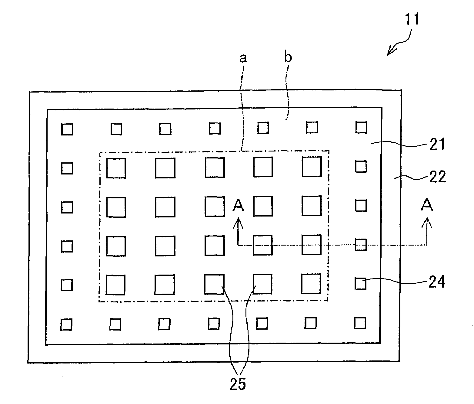
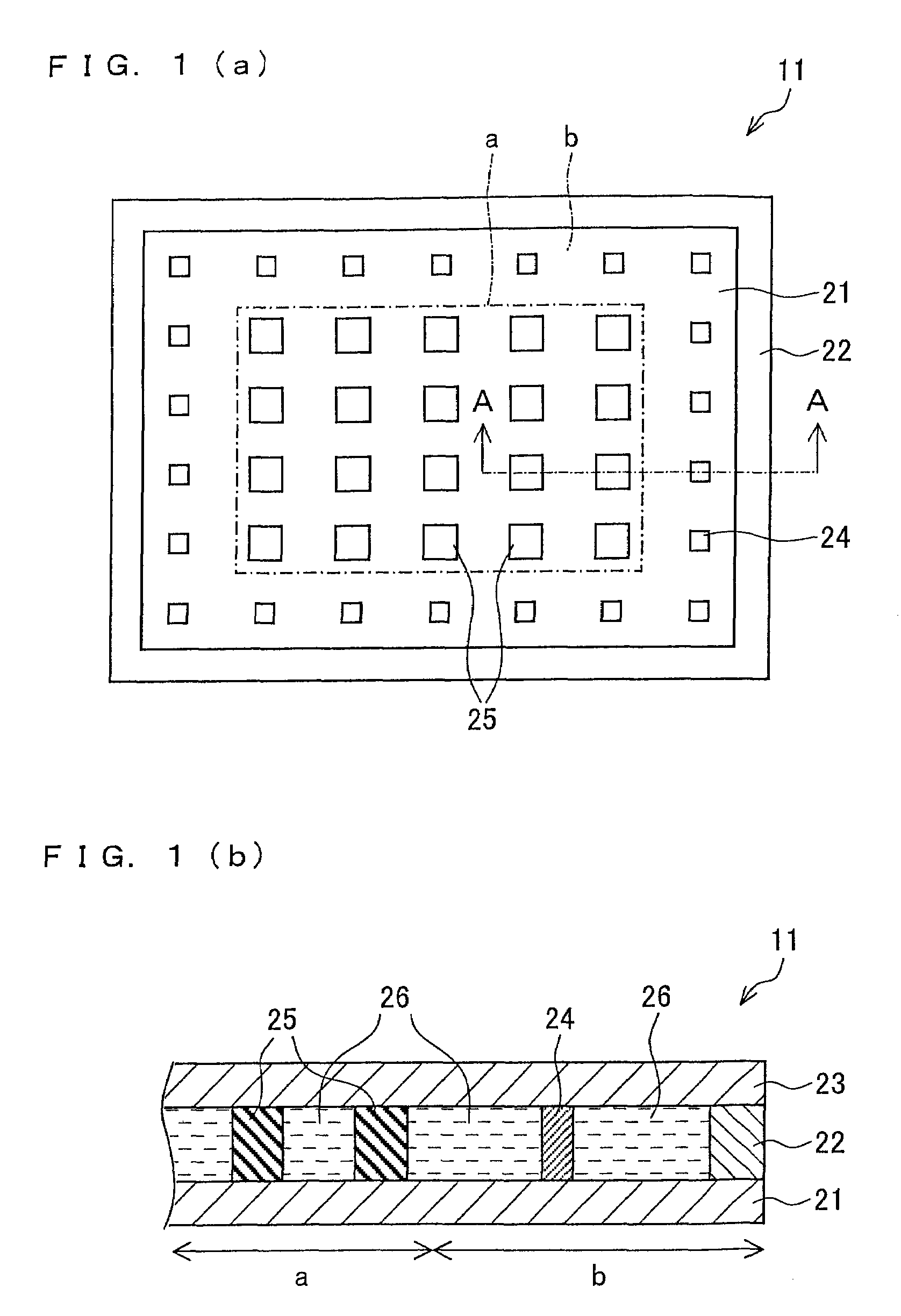
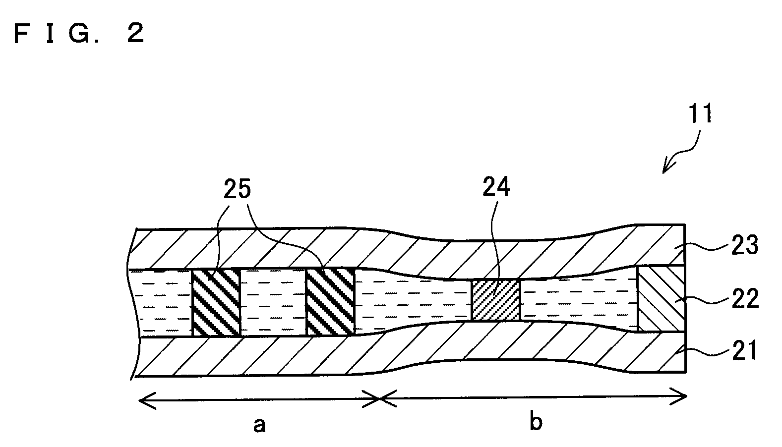
[0086]In this example, the first columnar spacers are provided across the whole panel so as to be each positioned in a black matrix portion of each pixel and so as to be each in the shape of an angular column having a height of 4.5 μm and an area of base of 10×20 μm. The height of the first columnar spacers is determined by the needed cell gap, and the area and density of the first columnar spacers are determined in accordance with substrate hardness and spacer elasticity so that the needed panel strength (needed degree of resistance to pressure) is obtained. The total area of the spacers is determined in this manner, and is usually not less than 0.5% per unit area. When it is not necessary to consider substrate deformation that is due to local external pressure, a uniform cell gap can be realized as long as the total area of the spacers is not less than 0.11%. However, in order to achieve such strength that external pressure such as pen-based input or the like are sufficiently with...

example 2

[0090]In this example, the first columnar spacers are provided across the whole panel so as to be each positioned in a black matrix portion of each pixel and so as to be each in the shape of an angular column having a height of 4.5 μm and an area of base of 10×20 μm. The height of the first columnar spacers is determined by the needed cell gap, and the area and density of the first columnar spacers are determined in accordance with substrate hardness and spacer elasticity so that the needed panel strength (needed degree of resistance to pressure) is obtained. The total area of the spacers is determined in this manner, and is usually not less than 0.5% per unit area. When it is not necessary to consider substrate deformation that is due to local external pressure, a uniform cell gap can be realized as long as the total area of the spacers is not less than 0.1%. However, in order to achieve such strength that external pressure such as pen-based input or the like are sufficiently withs...

example 3

[0094]In this example, the first columnar spacers are provided across the whole panel so as to be each positioned in a black matrix portion of each pixel and so as to be each in the shape of an angular column having a height of 4.5 μm and an area of base of 10×20 μm. The height of the first columnar spacers is determined by the needed cell gap, and the area and density of the first columnar spacers are determined in accordance with substrate hardness and spacer elasticity so that the needed panel strength (needed degree of resistance to pressure) is obtained. The total area of the spacers is determined in this manner, and is usually not less than 0.5% per unit area. When it is not necessary to consider a substrate deformation that is due to local external pressure, a uniform cell gap can be realized as long as the total area of the spacers is not less than 0.1%. However, in order to achieve such strength that external pressure such as pen-based input or the like are sufficiently wit...


PUM

PropertyMeasurementUnit
heightaaaaaaaaaa
heightaaaaaaaaaa
heightaaaaaaaaaa

Abstract

A liquid crystal display element includes two substrates divided into a display region and a non-display region, between which liquid crystals are sandwiched, and first columnar spacers, disposed between the two substrates in the display region, which make contact with the two substrates. The liquid crystal display element also includes second columnar spacers, disposed between the two substrates in the non-display region, which make contact with the two substrate by a contact area that is smaller than a contact area by which the first columnar spacers make contact with the two substrates. Therefore, generation of vacuum bubbles in the display region due to a temperature drop or a substrate deformation causes the substrates in the non-display region to be concaved, so that the liquid crystals move from the concaved portion of the non-display region to a portion of the display region which contains the vacuum bubbles. As a result, the vacuum bubbles in the display region can be filled with the liquid crystals, so that the vacuum bubbles can be eliminated from the display region.

Description

BACKGROUND OF THE INVENTION[0001]1. Field of the Invention[0002]The present invention relates to a liquid crystal display element that displays an image with use of liquid crystals sandwiched between substrates.[0003]2. Description of the Related Art[0004]As shown in FIGS. 12(a) and 12(b), a liquid crystal display element 101 constituting a conventional panel includes (i) two substrates (a lower substrate 121 and an upper substrate 123) divided into a display region a and a non-display region b and (ii) first columnar spacers 125, disposed between the substrates both in the display region a and the non-display region b, which make contact with the two substrates. Sandwiched between the two substrates are liquid crystals 126, and the liquid crystals 126 are sealed in with sealing material 122.[0005]A liquid crystal panel manufactured with the use of flexible substrates such as plastic substrates needs columnar spacers in order to obtain a predetermined cell gap, uniformity, and resis...

Claims


Application Information

Patent Timeline
Patent Type & Authority Patents(United States)
IPC IPC(8): G02F1/1339
CPCG02F1/13394G02F2001/133388G02F1/133388
Inventor WATANABE, NORIKO
Owner SHARP KK
Why Eureka
Try Eureka