Rolling element bearings for an oil-free liquid chiller

a technology of rolling element bearings and liquid chillers, which is applied in the direction of liquid fuel engines, machines/engines, light and heating apparatus, etc., can solve the problems of high initial and operational costs, unique and challenging bearing lubrication issues, and the lubrication of rotating components that has historically proven both challenging and expensive, and achieves enhanced compressor cooling and high operational speeds. , the effect of less mass

Inactive Publication Date: 2014-12-11
TRANE INT INC
View PDF2 Cites 31 Cited by
  • Summary
  • Abstract
  • Description
  • Claims
  • Application Information

AI Technical Summary

Benefits of technology

[0030]It is an additional object of the present invention to provide, an oil-free centrifugal chiller in which the centrifugal forces to which the bearings of the chiller are exposed, at high operational speeds, are reduced by the use of ceramic rolli

Problems solved by technology

The high speed rotation of such physically large and heavy chiller components at several thousand RPM results in unique and challenging bearing lubrication issues, particularly at start-up when these components are at rest, but also during chiller shutdown when these components coast to a stop.
In the cases of both direct drive and gear drive large tonnage centrifugal chillers, lubrication of their rotating components has historically proven both challenging and expensive and has been exclusively or at least fundamentally accomplished by the use of oil as the lubricant.
The need for such lubrication systems has vastly complicated the design, manufacture, operation, maintenance and control of centrifugal chillers of both the direct drive and gear drive type and has added great initial and operational cost to them.
As was noted earlier, however, gear drive machines do not offer many of the advantages of direct drive machines and their use brings several distinct disadvantages, the need for an oil-based lubrication system for the purpose of ensuring the adequate lubrication of the gear train being one of them.
Further, such bearings detract from the efficiency of the compressor's in which they are used as a result of the frictional losses that are inherent in such bearings as compared to the frictional loses associated with rolling element bearings.
While hydrodynamic and hydrostatic bearings lubricated by refrigerant may have been at least prospectively employed in specialized, relatively physically small capacity compressors, the use of such bearings in large tonnage centrifugal chillers poses significant difficulties due, among other things, to the masses and weights of the chiller impellers and shafts that must be rotationally started and supported in that applicati

Method used


Image

  • Rolling element bearings for an oil-free liquid chiller
  • Rolling element bearings for an oil-free liquid chiller
  • Rolling element bearings for an oil-free liquid chiller

Examples


Embodiment Construction

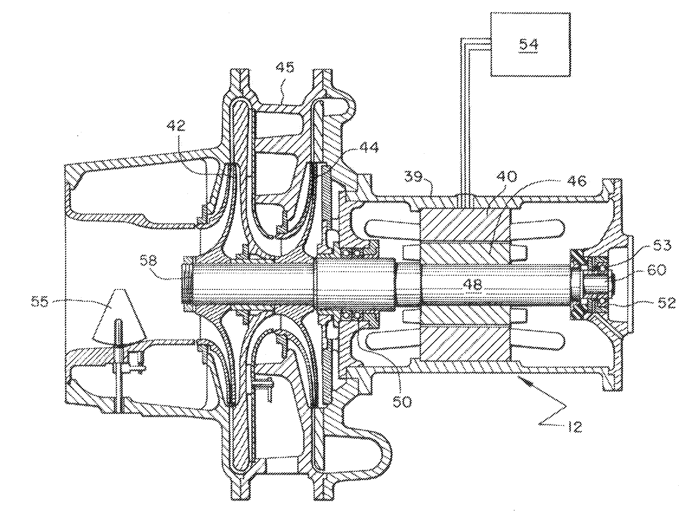
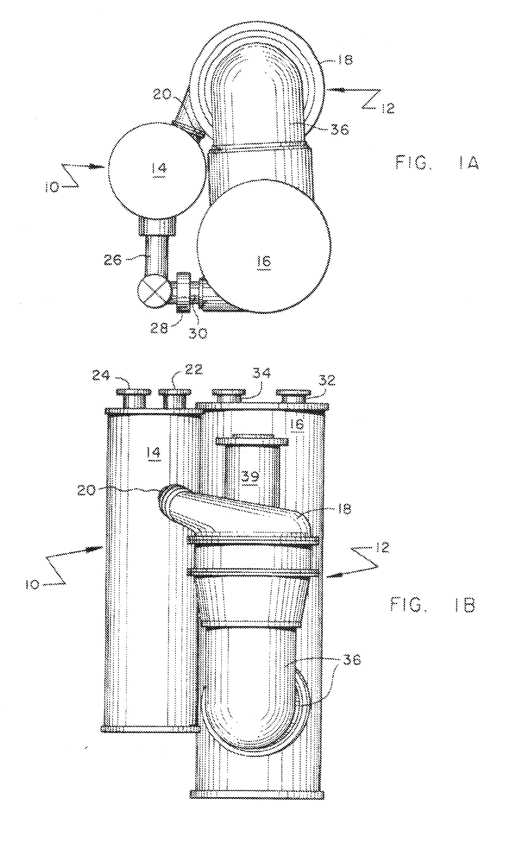
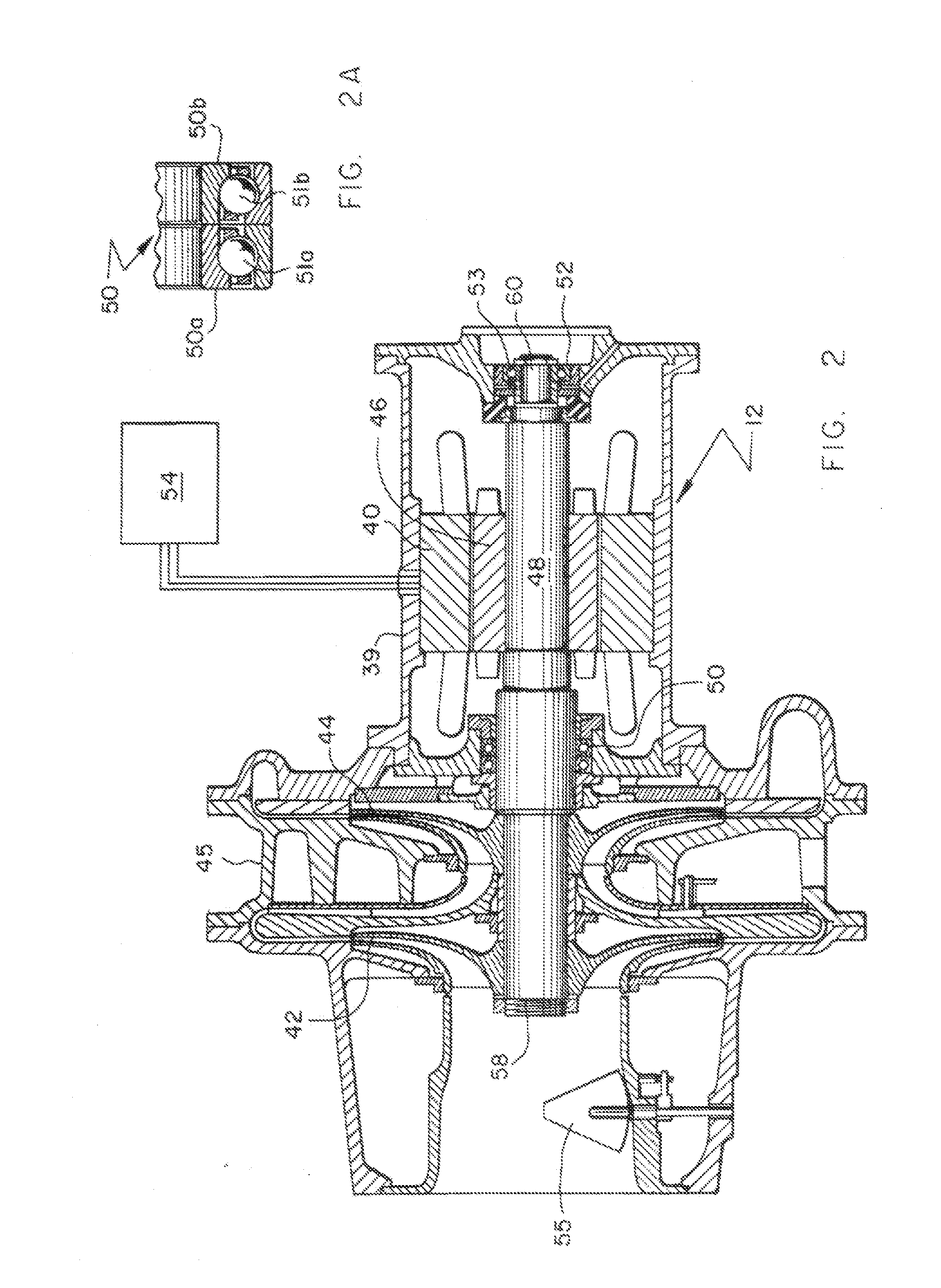
[0041]Referring to Drawing FIGS. 1a and 1b, a chiller 10, which in the preferred embodiment is a centrifugal chiller, and its basic components are illustrated. In that regard, chiller 10 is comprised of a compressor portion 12, a condenser 14 and an evaporator 16. Refrigerant gas is compressed within compressor portion 12. Such refrigerant gas is directed out of discharge volute 18 into piping 20 which connects the compressor to condenser 14.

[0042]Condenser 14 will typically be cooled by a liquid which enters the condenser through inlet 22 and exits through outlet 24. This liquid, which is typically city water or water that passes to, through and back from a cooling tower, exits the condenser after having been heated in a heat exchange relationship with the hot, compressed system refrigerant which is directed out of the compressor into the condenser in a gaseous state.

[0043]The heat exchange process occurring within condenser 14 causes the relatively hot, compressed refrigerant gas ...


PUM

PropertyMeasurementUnit
Fractionaaaaaaaaaa
Fractionaaaaaaaaaa
Fractionaaaaaaaaaa

Abstract

A refrigeration chiller employs a centrifugal compressor the impellers of which are mounted on a shaft which is itself mounted for rotation using rolling element bearings lubricated only by the refrigerant which constitutes the working fluid of the chiller system. Apparatus is taught for providing liquid refrigerant to (1.) the bearings immediately upon chiller start-up, during chiller operation and during a coastdown period subsequent to shutdown of the chiller and (2.) the drive motor of the chiller's compressor for motor cooling purposes. By use of a variable speed-driven motor to drive the compressor, optimized part load chiller performance is achieved in a chiller which does not require or employ an oil-based lubrication system.

Description

CROSS REFERENCE TO RELATED APPLICATIONS[0001]Currently does not apply: This application claims the benefit of provisional patent application serial number 00 / 000,000 filed on 00 / 00 / 0000 by the present inventor.BACKGROUND OF THE INVENTION[0002]This patent application may be related to a commonly assigned U.S. patent application filed on even date herewith entitled “Liquid Chiller with Enhanced Motor Cooling and Lubrication” as well as allowed and commonly assigned U.S. Pat. No. 5,848,538 entitled “Oil and Refrigerant Pump for Centrifugal Chiller” and any divisional applications that may derive therefrom.[0003]The present invention relates to liquid chillers. More particularly, the present invention relates to relatively large tonnage centrifugal chillers in which so-called hybrid bearings are employed and in which the lubrication of such bearings is by the refrigerant which comprises the chiller's working fluid. With still more particularity, the present invention relates to oil-free...

Claims


Application Information

Patent Timeline
IPC IPC(8): F25B31/00F16C43/04F16C33/62F25B1/00F16C33/64
CPCF25B31/002F25B31/006F25B1/005F16C2204/66F16C33/62F16C43/04F16C33/64F04D17/10F04D17/12F04D29/059F04D29/063F16C33/303F16C33/6692F25B1/053F16C2204/70F16C2360/44Y10T29/49689C22B9/003C22B9/04C22B9/18C22B9/20
Inventor LAPP, WILLIAM E.SMITH, TODD W.BUTTERWORTH, ARTHUR L.SIKORSKY, PAUL J.
Owner TRANE INT INC
Why Eureka
Try Eureka