
Method and apparatus for molding an upper and a lower mold having no flask, and a method for replacing a match plate used therefor

Active Publication Date: 2010-02-02
SINTOKOGIO LTD
View PDF14 Cites 5 Cited by
  • Summary
  • Abstract
  • Description
  • Claims
  • Application Information

AI Technical Summary

Benefits of technology

[0019]According to this invention, since a molding process to make the molds in a pair of the upper and the lower flask and a process to remove the molds which have already been made from the upper and the lower flask proceed simultaneously, it is possible to make an upper and a lower mold having no flask faster and more efficiently compared with the conventional method.
[0109]By the method according to the eighteenth invention, it is possible to replace the match plate faster and more efficiently compared with the conventional method.

Problems solved by technology

However, the conventional molding machine for molding an upper and a lower mold having no flask has problems to be solved, such as it is not efficient enough, it is necessary to improve the quality of the mold and the procedure for replacing the match plate, or the molding machine should be smaller.Patent document 1: Examined Japanese Patent Application Publication No.

Method used


Image

  • Method and apparatus for molding an upper and a lower mold having no flask, and a method for replacing a match plate used therefor
  • Method and apparatus for molding an upper and a lower mold having no flask, and a method for replacing a match plate used therefor
  • Method and apparatus for molding an upper and a lower mold having no flask, and a method for replacing a match plate used therefor

Examples


Embodiment Construction

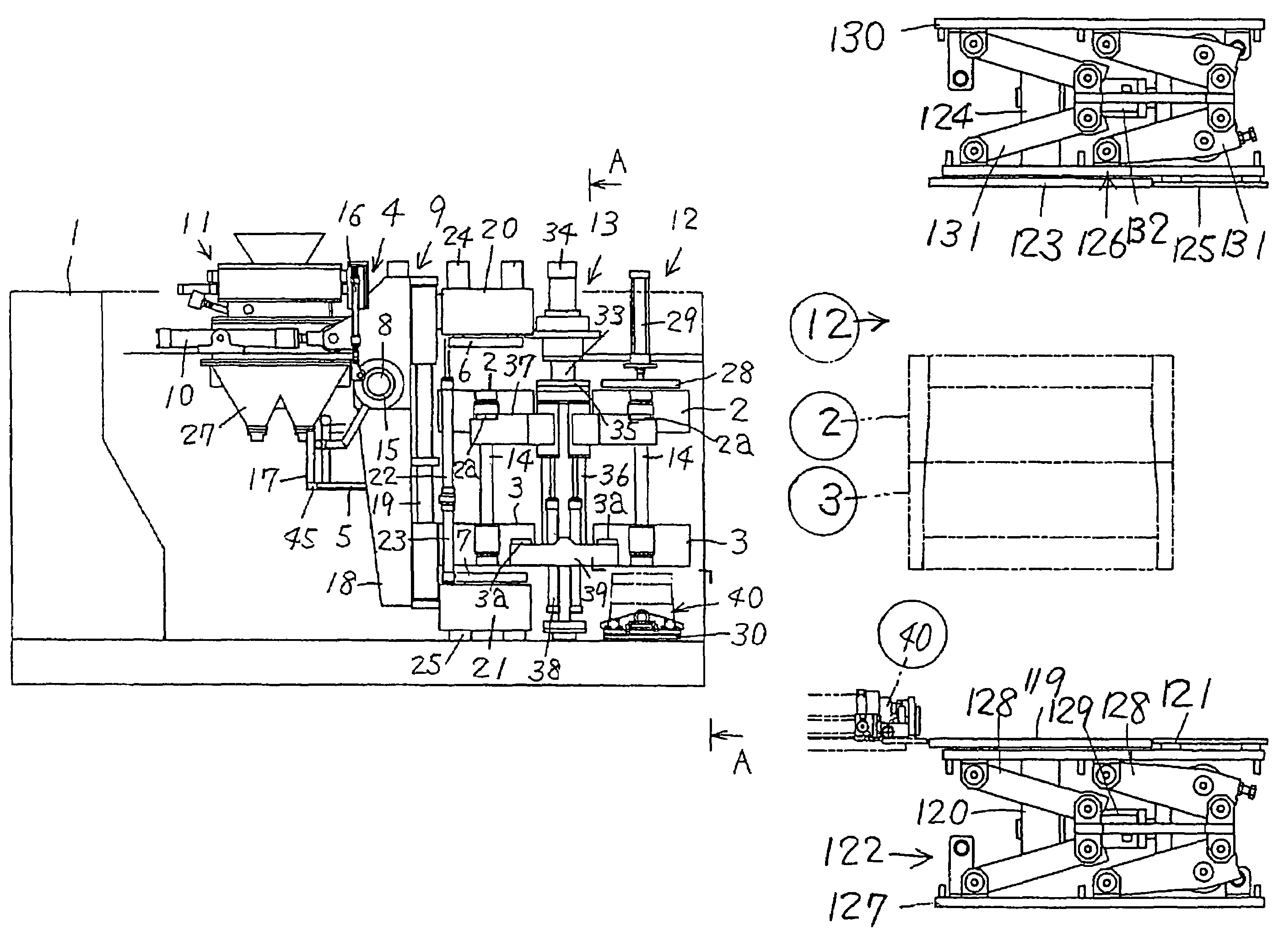
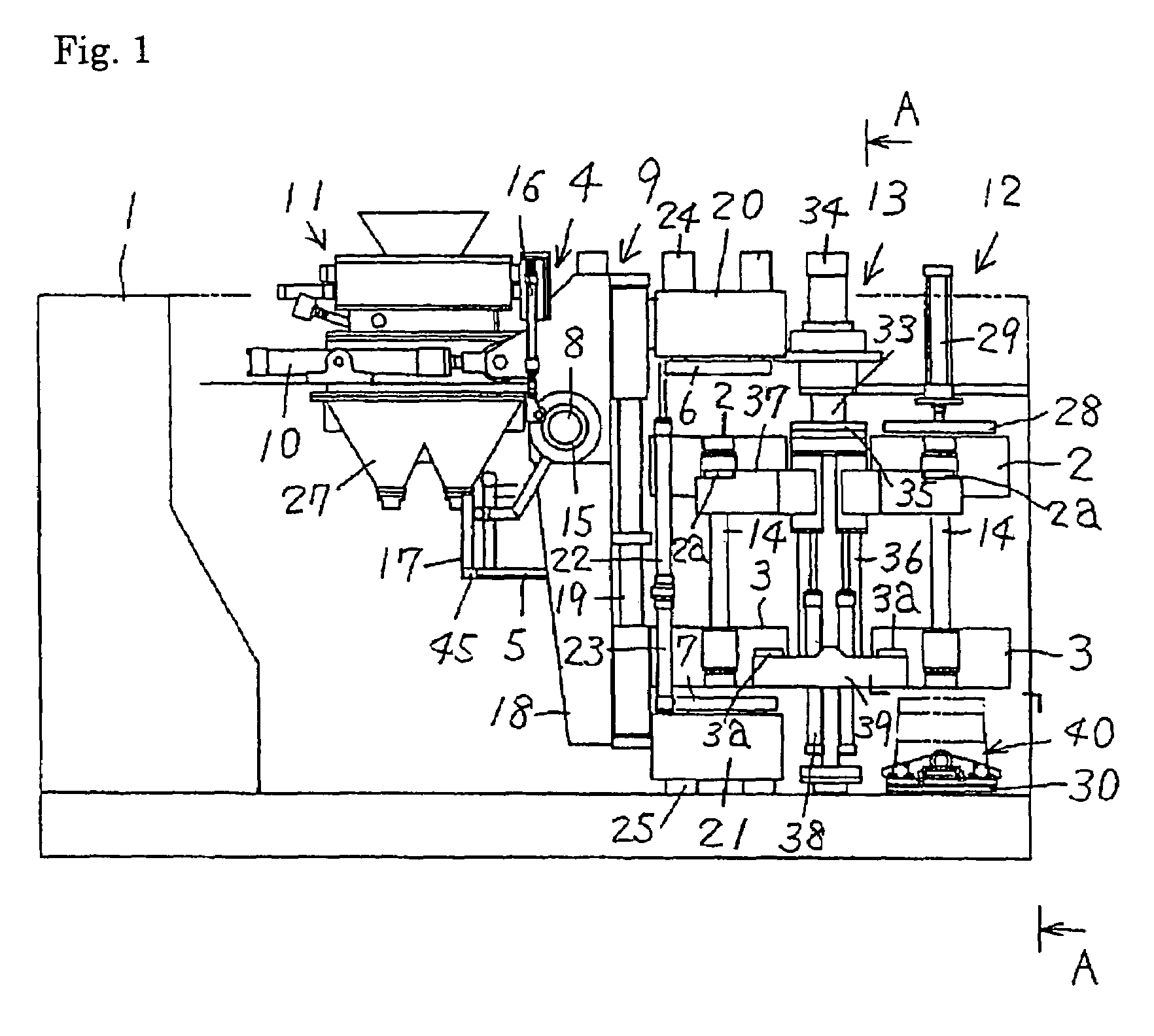
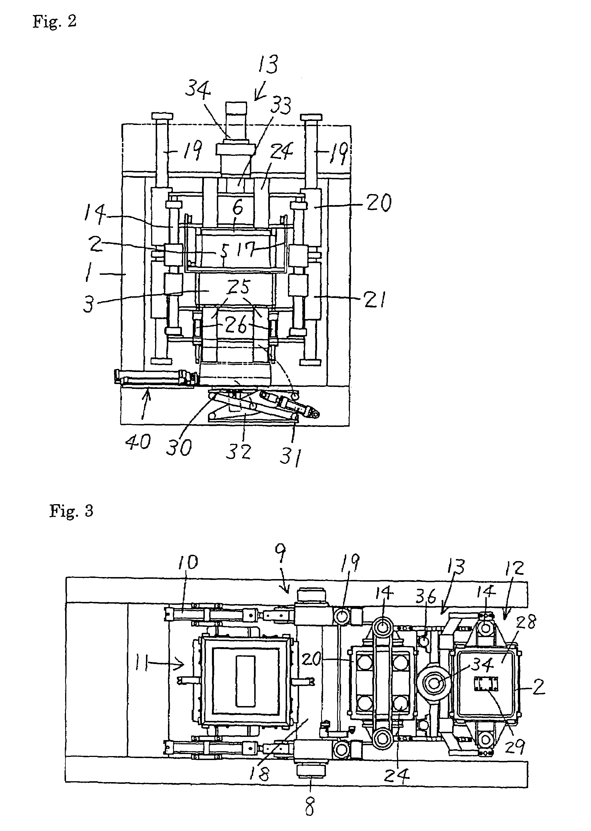
[0135]Embodiments of this invention for an apparatus for molding an upper and a lower mold having no flask are now explained in detail based on the figures.

[0136]FIGS. 1-3 show an apparatus for molding an upper and a lower mold having no flask, using an upper and a lower squeeze plate as the upper and the lower squeeze means.

[0137]The apparatus for molding the upper and the lower mold having no flask includes:

[0138]a base 1 having an internal space and a rectangular parallelepiped configuration,

[0139]two pairs of an upper and a lower flask 2, 3, 2, 3 having intakes disposed at their side walls for foundry sand,

[0140]a match plate 5 disposed between one of the two pairs of the upper and the lower flask 2, 3, 2, 3 so that the match plate can be inserted and taken out by a conveying apparatus 4,

[0141]a squeezing mechanism 9 to squeeze the foundry sand, which supports a pair of the upper and the lower flask 2, 3 having the match plate 5 between the upper and the lower flask 2, 3, which ...


PUM

PropertyMeasurementUnit
moldingaaaaaaaaaa
distanceaaaaaaaaaa
molding spaceaaaaaaaaaa

Abstract

A method and apparatus for molding molds having no flask wherein a match plate is put between an upper and a lower flask having intakes for foundry sand. An upper and a lower molding space are defined by inserting an upper and a lower squeeze device into openings of a pair of the upper and the lower flask having no match plate, and a pair of the upper and the lower flask and the match plate are rotated and moved so that they become perpendicular, and are moved so that the intakes of the flasks move upward. The upper and the lower molding space are filled with the foundry sand. The foundry sand in the molding spaces is squeezed by the squeeze devices. A pair of the flasks and the match plate are rotated so that they become horizontal. Then the match plate is removed. While the preceding processes are being carried out, if necessary a core can be installed between the molds, the flasks are matched to each other, and the molds are removed from the pair of flasks.

Description

TECHNICAL FIELD[0001]This invention relates to a method and apparatus for molding an upper and a lower mold having no flask. Further, it relates to a method and apparatus for replacing a match plate used therefor.BACKGROUND OF THE INVENTION[0002]Conventionally, as one of the molding machines of this type, there is the following apparatus, comprising:[0003]a first station, which is disposed above a base, for compressing foundry sand in a molding space by squeezing the sand in a horizontal direction,[0004]a second station, which is disposed near a lower surface of the base, for matching an upper mold with a lower mold in a perpendicular direction against the lower surface of the base and for removing flasks,[0005]wherein two sets of the upper and the lower flask are alternately reciprocated between the first and the second station, and wherein an upper and a lower mold that match each other and that have no flask are molded.[0006]However, the conventional molding machine for molding a...

Claims


Application Information

Patent Timeline
Patent Type & Authority Patents(United States)
IPC IPC(8): B22C9/00B22C17/00B22C15/02B22C15/24B22C11/00B22C11/10
CPCB22C11/10B22C11/00
Inventor HIRATA, MINORUKOMIYAMA, TAKAYUKI
Owner SINTOKOGIO LTD
Learn More