Desuperheater spray nozzle

a superheating and spray nozzle technology, applied in the direction of check valves, machines/engines, combustible gas purification/modification, etc., can solve the problems of uneven and poorly controlled temperature reduction throughout the flow of the superheating, water buildup, structural failure, etc., to improve the absorption and evaporation efficiency of the cooling water, and the effect of simple manufacturing

Active Publication Date: 2010-02-02
CONTROL COMPONENTS INC
View PDF22 Cites 20 Cited by
  • Summary
  • Abstract
  • Description
  • Claims
  • Application Information

AI Technical Summary

Benefits of technology

[0016]In the valve body, the fracture ring is disposed in spaced relation to the lower edge of the nozzle cone which circumvents the bottom surface thereof. In this regard, a series of windows are formed in the valve body, with each window being framed by a segment of the lower edge of the nozzle cone, an adjacent pair of the ribs, and a segment of the top edge of the fracture ring. The edges of the windows are sharp to cut the sheet flow leaving the outer surface of the nozzle cone, with the sharp edges being important to reducing droplet sizes from the valve element and hence the nozzle assembly.
[0017]The fracture ring of the valve body has a delta wedge cross-sectional configuration, with the apex of such wedge preferably intersecting the tangent line from the lower edge of the nozzle cone. Similarly, each of the ribs preferably has a delta wedge cross-sectional configuration, with the apex of the ribs continuing inwardly toward the axis of the valve element until the ribs are ultimately connected to the hub formed on the bottom surface of the nozzle cone. The integral connection of the ribs to the hub and thus the nozzle cone significantly improves the mechanical strength of the ribs and the fracture ring integrally connected to the ribs. The internal surfaces of the valve body defined by the ribs, fracture ring, hub and nozzle cone have no square corners or intersections, the elimination of which prevents the formation of streaks in the sheet flow leaving the valve element. Those of ordinary skill in the art will appreciate that the generation of such streaks in turn creates undesirable large droplets at lower nozzle flow rates.
[0018]In accordance with another embodiment of the valve element of the present invention, the outer end surface of each of the ribs may be stepped relative to the lower edge of the nozzle cone. This is in contrast to the aforementioned embodiment which is an in-line profile wherein the outer surface of the fracture ring, the outer surfaces of the ribs, and the outer surface of the nozzle cone are substantially flush or continuous with each other as indicated above. With the stepped profile, the outer surfaces of the fracture ring and ribs, while being substantially flush or continuous with each other, are at a slightly acute angle relative to the outer surface of the nozzle cone, and thus intersect the nozzle cone at a step beneath the same. The purpose of the stepped profile is to generate a detached sheet flow at lower flow rates. The sheet flow is split at the fracture ring, with the differential angle diverting a portion of the flow outward radially, thus increasing the cone area of the spray. In contrast, with the in-line profile, the tangent or continuous outer surfaces of the fracture ring, ribs and nozzle cone minimize disruption to the sheet flow, especially at low nozzle flow rates.
[0020]Despite the somewhat complex geometries of the valve elements constructed in accordance with the present invention, such valve elements can be manufactured quite simply. The internal tapered profiles and curved elliptical paths of the profiles are generated by machining the valve body with a simple tapered profile tool on a CNC machine. This represents a significant improvement over prior art valve element designs which are often too difficult to manufacture without compromising performance and strength.
[0021]In each embodiment of the valve element of the present invention, a portion of the outer surface of the nozzle cone is configured to be complimentary to the valve seat of the nozzle assembly such that the engagement of the outer surface of the nozzle cone to valve seat defined by the lower portion of the nozzle housing effectively blocks the flow of cooling water out of the nozzle assembly when the valve element is in the closed position. Conversely, when the valve element is axially moved from the closed position to the open position, cooling water is able to flow downwardly through an annular gap collectively defined by the outer surface of the nozzle cone and the valve seat. The combination of the conical valve seat and conical outer surface is effective to induce a conical spray pattern for the cooling water that is exiting the annular gap when the valve element is in the open position. As the film of cooling water flows downwardly over the outer surface of the nozzle cone of the valve body, a portion of the cooling water sheet impinges the fracture ring, with all of the cooling water eventually entering into the flow of super heated steam passing through the steam pipe.
[0022]As a result of the structural and functional attributes of the valve elements constructed in accordance with each embodiment of the present invention, cooling water droplet size is kept to a minimum, thus improving the absorption and evaporation efficiency of the cooling water within the flow of superheated steam, in addition to improving the spatial distribution of the cooling water. In this regard, the structural and functional attributes of the valve elements constructed in accordance with the present invention are operative to induce a conical spray pattern for the coolant water that is generated from the spray nozzle assembly when the valve element is in the open position, with the passage of a portion of the cooling water sheet over the fracture ring providing the desirable lower droplet size attributes describes above.

Problems solved by technology

Because superheated steam can damage turbines or other downstream components, it is necessary to control the temperature of the steam.
In addition, a streaming spray of cooling water will pass through the superheated steam flow and impact the opposite side of the steam pipe, resulting in water buildup.
This water buildup can cause erosion and thermal stresses in the steam pipe that may lead to structural failure.
Conversely, a non-uniform spray pattern of cooling water will result in an uneven and poorly controlled temperature reduction throughout the flow of the superheated steam.
Along these lines, the inability of the cooling water spray to efficiently evaporate in the superheated steam flow may also result in an accumulation of cooling water within the steam pipe.
The accumulation of this cooling water will eventually evaporate in a non-uniform heat exchange between the water and the superheated steam, resulting in a poorly controlled temperature reduction.

Method used


Image

  • Desuperheater spray nozzle
  • Desuperheater spray nozzle
  • Desuperheater spray nozzle

Examples


second embodiment

[0063]Referring now to FIGS. 7 and 8, there is shown a valve element 78a constructed in accordance with the present invention. The valve element 78a is substantially similar in structure and function to the above-described valve element 78, with only the distinctions between the valve elements 78, 78a being highlighted below.

[0064]The sole distinction between the valve elements 78, 78a lies in the outer end surface of each of the ribs 96a in the valve element 78a being stepped relative to the lower edge 92a of he nozzle cone 86a thereof. This is in contrast to the valve element 78 which is an in-line profile wherein the outer surface of the fracture ring 98, the outer end surfaces of the ribs 96, and the outer surface 88 of the nozzle cone 86 are substantially flush or continuous with each other as indicated above. With the stepped profile, the outer surfaces of the fracture ring 98a and ribs 96a, while being substantially flush or continuous with each other, are at a slightly acute...

third embodiment

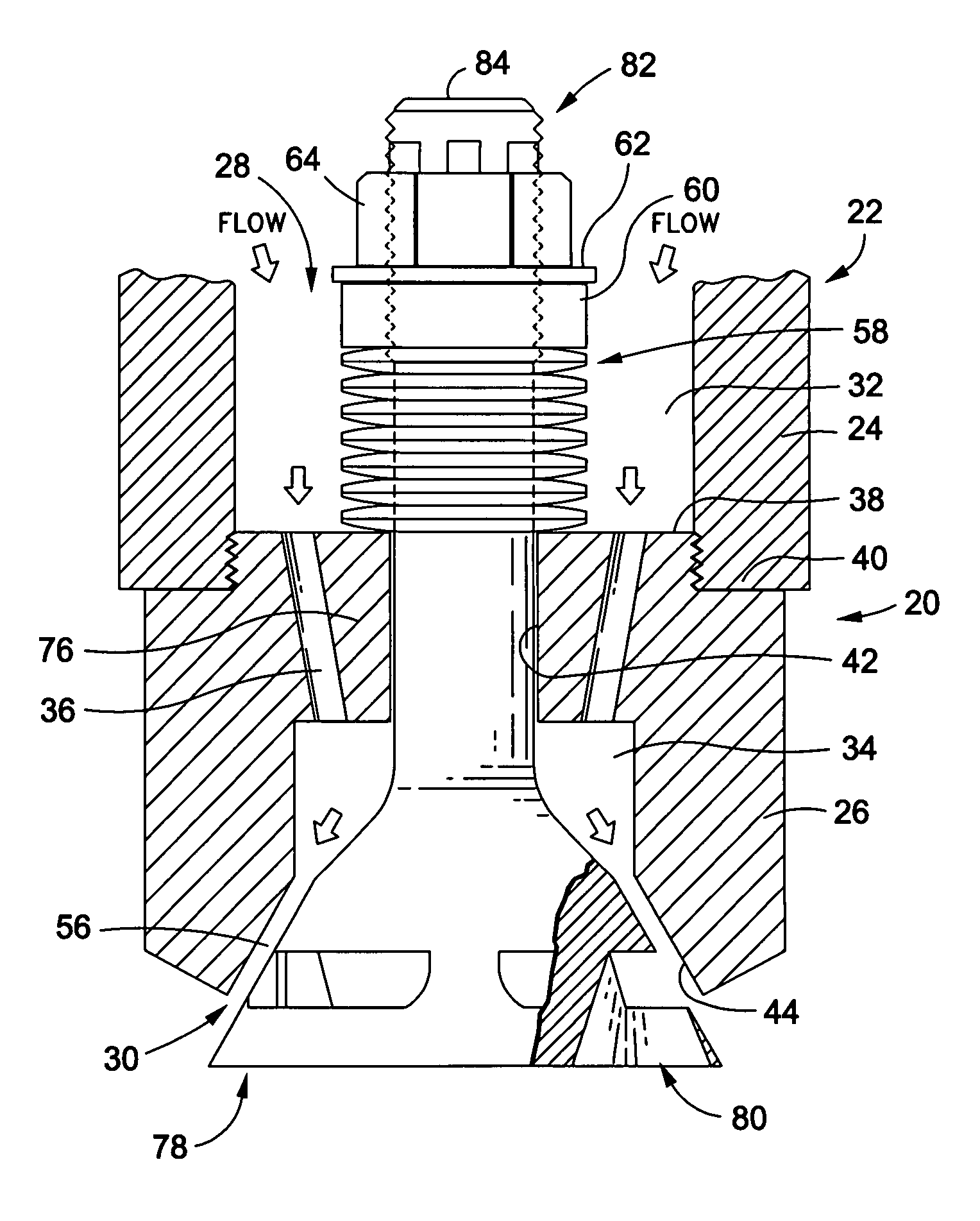
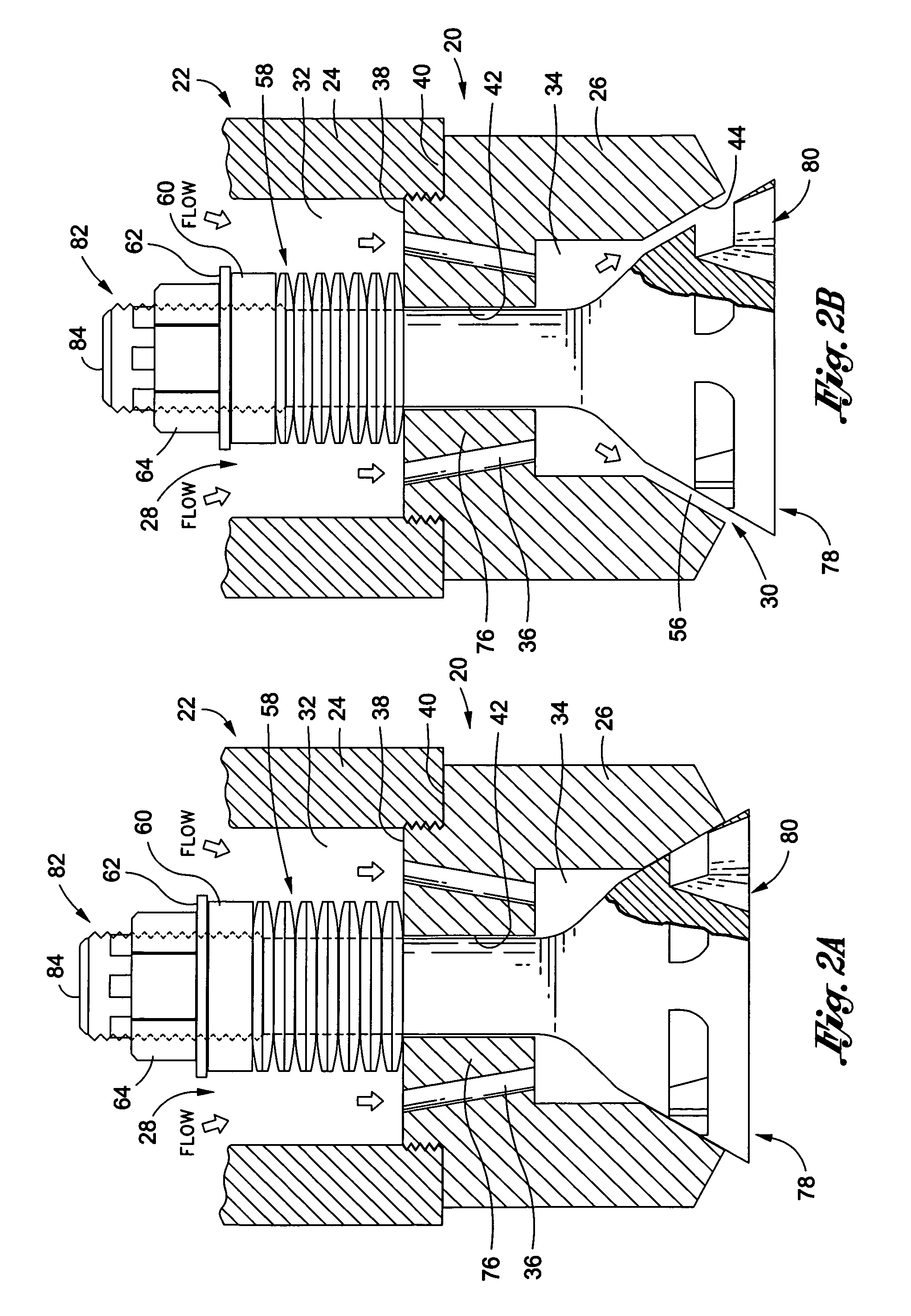
[0065]Referring now to FIGS. 9-13, there is shown a valve element 106 constructed in accordance with the present invention. The valve element 106 comprises a valve body 108 and an elongate valve stem 110 which is integrally attached to the valve body 108 and extends axially therefrom. The valve stem 110 has a generally circular cross-sectional configuration, and defines a distal end 112. It is contemplated that a distal portion of the valve stem 110 extending to the distal end 112 thereof may be externally threaded for purposes of facilitating the operative interface of the valve element 106 into the above-described nozzle assembly 20. The valve stem 110, like the valve stem 82 of the valve element 78, is sized and configured to be slidably advanceable through the valve stem bore 42 of the nozzle housing 22. In this regard, the valve stem 110 is sized and configured to be complimentary to the valve stem bore 42 such that an axially sliding fit is provided therebetween. This allows t...


PUM

PropertyMeasurementUnit
half angleaaaaaaaaaa
temperatureaaaaaaaaaa

Abstract

An improved valve element for a spray nozzle assembly of a steam desuperheating device that is configured to spray cooling water into a flow of superheated steam in a generally uniformly distributed spray pattern. The valve element includes a valve body and an elongate valve stem that is integrally attached to the valve body and extends axially therefrom. The valve body itself includes a nozzle cone which is integrally connected to the valve stem, and defines an outer surface. Integrally formed on a bottom surface of the nozzle cone is a hub having multiple ribs protruding therefrom. Integrally connected to each of the ribs is a generally circular fracture ring. The fracture ring is disposed in spaced relation to the lower edge of the nozzle cone which circumvents the bottom surface thereof. In this regard, a series of windows are formed in the valve body, with each window being framed by a segment of the lower edge of the nozzle cone, an adjacent pair of the ribs, and a segment of the top edge of the fracture ring.

Description

CROSS-REFERENCE TO RELATED APPLICATIONS[0001]Not ApplicableSTATEMENT RE: FEDERALLY SPONSORED RESEARCH / DEVELOPMENT[0002]Not ApplicableBACKGROUND OF THE INVENTION[0003]1. Field of the Invention[0004]The present invention pertains generally to steam desuperheaters and, more particularly, to a uniquely configured valve element for use in a spray nozzle assembly for a steam desuperheating device. The nozzle assembly is specifically adapted for creating a substantially uniformly distributed spray of cooling water for spraying into a flow of superheated steam in order to reduce the temperature thereof.[0005]2. Description of the Related Art[0006]Many industrial facilities operate with superheated steam that has a higher temperature than its saturation temperature at a given pressure. Because superheated steam can damage turbines or other downstream components, it is necessary to control the temperature of the steam. Desuperheating refers to the process of reducing the temperature of the su...

Claims


Application Information

Patent Timeline
Patent Type & Authority Patents(United States)
IPC IPC(8): B01F3/04B05B15/06
CPCB05B1/06F22G5/123B05B1/304Y10S261/13B05B1/3073Y10T137/7932
Inventor FREITAS, STEPHEN G.SELZER, ORY D.NEWTON, RAYMOND R.
Owner CONTROL COMPONENTS INC
Why Eureka
Try Eureka