Solar-rechargeable light

a solar energy and light technology, applied in the field of solar energy rechargeable and visible light producing structures, can solve the problems of limited placement of display signs such as billboards, and achieve the effects of reducing energy stored, maintaining effective illumination brightness, and energy storage devices

Inactive Publication Date: 2010-02-02
WIGHT ROBERT M +2
View PDF4 Cites 62 Cited by
  • Summary
  • Abstract
  • Description
  • Claims
  • Application Information

AI Technical Summary

Benefits of technology

[0007]The present invention provides a solar-rechargeable light fixture adapted to be recharged by the sun during the day, and to emit light for a period of time after dusk. Embodiments of the invention may be arranged to provide 8 to 12 hours, or even more in certain cases, of additional time during a 24-hour day in which a sign may be visually observed. An exemplary embodiment of the invention provides a solar-rechargeable light fixture that is configured and arranged to illuminate both sides of a residential, yard-mounted, real estate sign. The exemplary embodiment may be used to extend the period of time during which a real estate sign is visible to potential clients. The illuminated real estate sign provides an eye-catching attraction after dark to passers-by.
[0015]As an energy management scheme, the microprocessor may be programmed to cause a first approximately uniform and sub-maximum electrical output, from the energy storage device to the first light-emitting element, which is effective to maintain effective illumination brightness of an output from the first light-emitting element at a first substantially uniform value, during a first extended period of time during which a reduction of energy stored in the energy storage device occurs. Also, the microprocessor can be programmed to cause a second approximately uniform and sub-maximum electrical output, from the energy storage device to the first light-emitting element, which is effective to maintain effective illumination brightness of an output from the first light-emitting element at a second substantially uniform value, during a second extended period of time during which a further reduction of energy stored in the energy storage device occurs.

Problems solved by technology

Therefore, placement of a display sign such as a billboard is limited by the proximity of, and ability to make a connection to, an electrical utility source.

Method used


Image

  • Solar-rechargeable light
  • Solar-rechargeable light
  • Solar-rechargeable light

Examples


Embodiment Construction

[0029]Reference will now be made to the drawings in which the various elements of the illustrated embodiments will be given numerical designations and in which the invention will be discussed so as to enable one skilled in the art to make and use the invention. It is to be understood that the following description is only exemplary of the principles of the present invention, and should not be viewed as narrowing the claims which follow.

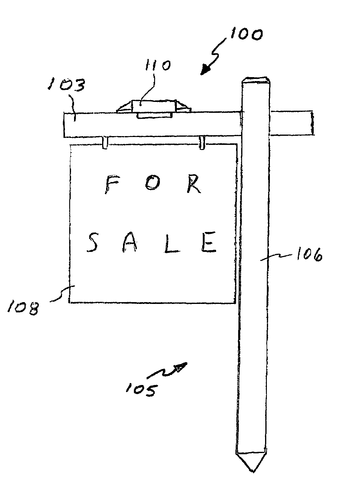
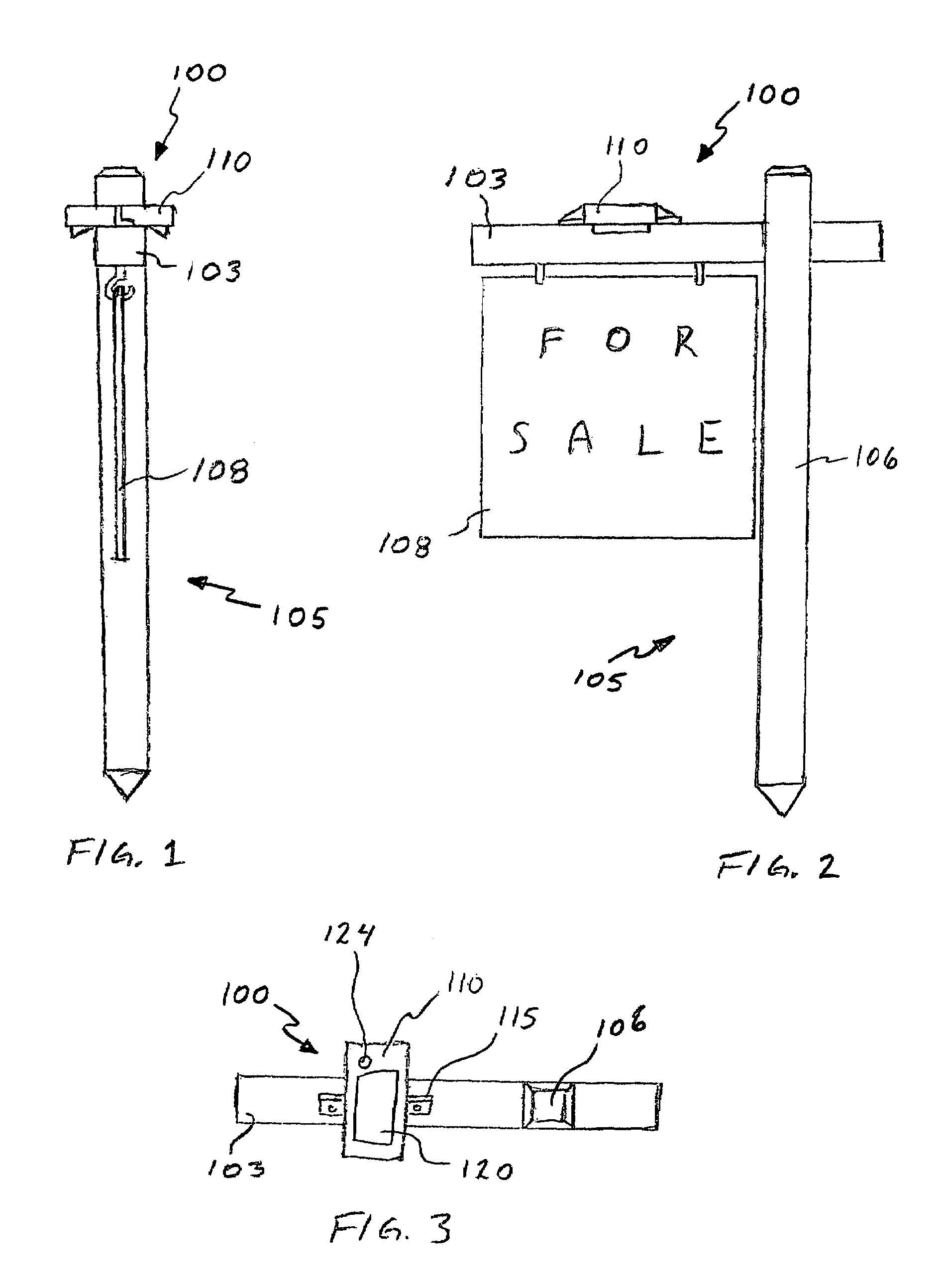
[0030]A first embodiment of a light fixture structured according to principles of the invention is illustrated in FIGS. 1-3, and is generally indicated at 100. Light fixture 100 is adapted for anchoring to a cross-bar 103 of a commercially available real estate sign, generally indicated at 105. The illustrated real estate sign 105 is representative of the residential yard-mounted type, and includes a vertical member 106 and cross-bar 103, which are typically made from dimensional lumber, such as wooden posts having a 4-inch by 4-inch cross-section. In...


PUM


Abstract

A solar-rechargeable light fixture. A preferred embodiment is adapted for attachment to the horizontal cross-bar of a yard-mounted real estate sign effective to illuminate both sides of the sign after dark. The light fixture includes a solar panel adapted to charge a battery which powers a plurality of lights, such as incandescent bulbs or LEDs. Sometimes, a microprocessor is included in-circuit to control operation of the light fixture, and may also provide diagnostic feedback to a user. Desirably, the light fixture can be switched into a storage mode to avoid discharge of the battery during periods of non-use.

Description

RELATED APPLICATIONS[0001]This application claims the benefit under 35 U.S.C. 119(e) of the filing date of Provisional Application Ser. No. 60 / 667,607, filed Apr. 1, 2005, for “SOLAR RECHARGEABLE LIGHT”, the entire disclosure of which is hereby incorporated as though set forth herein.BACKGROUND[0002]1. Field of the Invention[0003]This invention relates to apparatus operable to produce humanly visible light responsive to a low-light environment. In particular, the invention relates to electrically powered, solar-rechargeable, visible light-producing structures.[0004]2. State of the Art[0005]Lighting is known that is adapted to illuminate a single-sided display sign, such as a billboard. Such lighting generally includes one or more lamp in a light fixture that is typically hard-wired into electrical power delivered from an electrical utility. Therefore, placement of a display sign such as a billboard is limited by the proximity of, and ability to make a connection to, an electrical ut...

Claims


Application Information

Patent Timeline
Patent Type & Authority Patents(United States)
IPC IPC(8): F21L13/00
CPCG09F13/02G09F13/22F21S9/03G09F2007/005G09F2013/222Y10S362/812
Inventor WIGHT, ROBERT M.ROHBOCK, JAMES A.ASHBY, DARREN C.
Owner WIGHT ROBERT M
Why Eureka
Try Eureka