
Optical pumping device and method

a pumping device and optical technology, applied in the direction of lasers, time interval measurement, automatic control of pulses, etc., can solve the problems of atomic signal-to-noise ratio, atomic resonator performance is adverse, and the solution, although effective, proves difficult and complex to apply, so as to achieve the effect of suppressing the black state and destroying the black state more effectively

Active Publication Date: 2010-02-02
CSEM CENT SUISSE DELECTRONIQUE & DE MICROTECHNIQUE SA RECH & DEV
View PDF4 Cites 0 Cited by
  • Summary
  • Abstract
  • Description
  • Claims
  • Application Information

AI Technical Summary

Benefits of technology

The present invention proposes an optical pumping method that scrams the polarization to suppress the black states produced by the optical pumping method. This method is simple and does not require a stationary wave with zero angular momentum, an intense magnetic field, or a large number of optical frequencies. It destroys the black states more effectively than the method of Shirley et al. because the particles pass through a larger polarization gradient. The invention also includes a device for applying this method with means for achieving depolarization of the light radiation.

Problems solved by technology

(IEEE Transactions on Instrumentation and Measurement, 42 (2), April 1993, 115-120) have demonstrated on an experiment with an atomic cesium jet pumped by a laser, that the noise added by the residual fraction of atoms trapped in the black states may considerably reduce the atomic signal-to-noise ratio and therefore become detrimental to the performance of an atomic resonator.
This solution, although effective, proves to be difficult and complex to apply because of the requirement of several contiguous magnetic field areas with very different intensities (ten times weaker between the pumping areas than in the latter).
Unfortunately, the selection of such a transition strongly reduces the degrees of freedom for optimizing other parameters (hyperfine optical pumping efficiency and fluorescence rate).
Further, the availability of performing laser sources at these wavelengths is not guaranteed.
This solution, certainly elegant, nevertheless has the drawback of introducing two additional optical components with respect to the standard configuration.
Further, it is not totally effective if the polarization gradient is perfectly perpendicular to the atomic jet, which is the case in the standard configuration of the atomic clock.

Method used


Image

  • Optical pumping device and method
  • Optical pumping device and method
  • Optical pumping device and method

Examples


Embodiment Construction

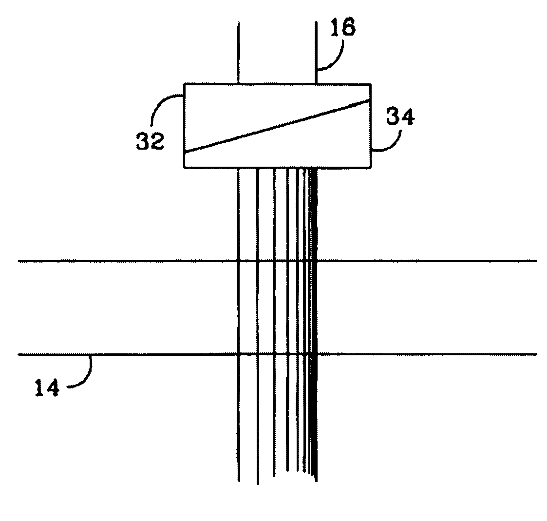
[0024]FIG. 5 schematically illustrates the area for preparing the atomic jet in an enlarged view. The beam 16 crosses the atomic jet 14 in order to perform optical pumping. A birefringent plate 32, for example in crystalline quartz, with non-parallel faces, is inserted on the path of the beam 16, upstream from the atomic jet 14. The orientation of the optical axis of the plate 32 relatively to the polarization of the incident beam 16 is such that it creates a maximum of ellipticity of the output polarization, ideally of 45° between the axis of the incident linear polarization and the principle axes of the birefringent plate. The phase gradient accumulated by the incident plane wave 16 due to the change in thickness of the plate 32, combined with the ellipticity of the polarization due to the double refractive index of the birefringent plate 32, produces a polarization gradient of the light beam transverse to the direction of propagation of the light beam 16. Further, the orientation...


PUM


Abstract

A method for optical pumping of particles and a device for implementing same. The particles (14) are changed from one long lifetime level to another long lifetime level via a short lifetime level by means of interaction with light radiation (16) emitted by a laser source. Prior to this interaction, the light radiation undergoes depolarization in a direction that is essentially perpendicular to the direction of propagation thereof, so as to reduce the entrapment of particles (14) in the black state.

Description

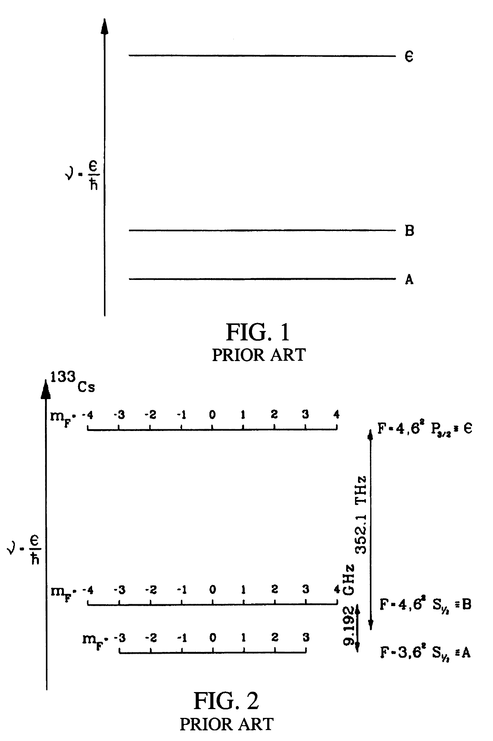
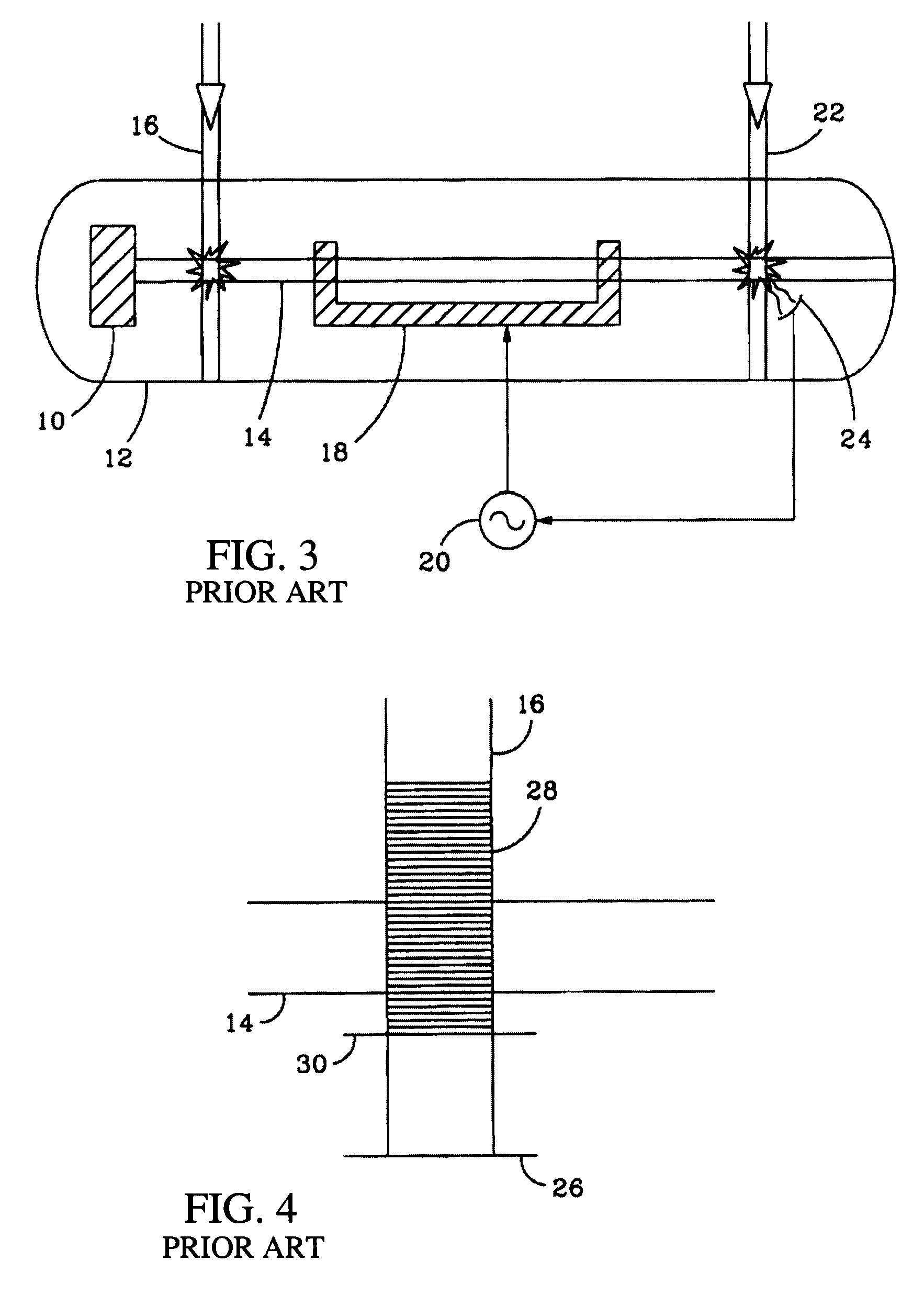
BACKGROUND OF THE INVENTION[0001]1) Field of the Invention[0002]The invention relates to a method for optical pumping of a set of particles such as atoms, ions, molecules or other particles, with which formation of black states may be avoided. It also relates to a device for applying this method.[0003]The invention finds interesting applications in atomic resonators and generally in all the instruments which use a source of particles and at least one laser beam capable of performing optical pumping of these particles. A particularly representative application is the atomic clock with an optically pumped cesium jet, the principle of operation of which is described later on. However, this example would not be able to limit the scope of the invention.[0004]2) Description of Related Art[0005]A particle may be characterized from the energy point of view, by discrete levels with a variable lifetime. FIG. 1 in a simplified way, schematically shows a representation of a particle having a le...

Claims


Application Information

Patent Timeline
Patent Type & Authority Patents(United States)
IPC IPC(8): H03L7/26H01S1/06H03B17/00
CPCG04F5/145H03L7/26
Inventor BERTHOUD, PATRICKTHOMANN, PIERRE
Owner CSEM CENT SUISSE DELECTRONIQUE & DE MICROTECHNIQUE SA RECH & DEV
Learn More