Eureka AIR delivers breakthrough ideas for toughest innovation challenges, trusted by R&D personnel around the world.

Servo-controlling method of an optical disk apparatus

a technology of optical disk and servo operation, which is applied in the direction of digital signal error detection/correction, instruments, recording signal processing, etc., can solve the problem of achieve the effect of effectively preventing fatal errors in servo operation

Inactive Publication Date: 2010-02-02
LG ELECTRONICS INC
View PDF20 Cites 1 Cited by
  • Summary
  • Abstract
  • Description
  • Claims
  • Application Information

AI Technical Summary

Benefits of technology

[0014]In the servo-controlling method with the above-stated characteristics according to the present invention, collision between the optical disk and the optical pickup of the optical disk apparatus is prevented, and thus the optical disk or the optical disk apparatus is not damaged. Furthermore, fatal errors in the servo operations are effectively prevented.

Problems solved by technology

Consequently, the object lens OL of the optical pickup 14 of the optical disk apparatus comes into collision with the CD 20, which may cause the CD 20 or the object lens OL of the optical pickup 14 to be damaged, or otherwise cause the servo operation to have fatal errors.

Method used


Image

  • Servo-controlling method of an optical disk apparatus
  • Servo-controlling method of an optical disk apparatus
  • Servo-controlling method of an optical disk apparatus

Examples


Embodiment Construction

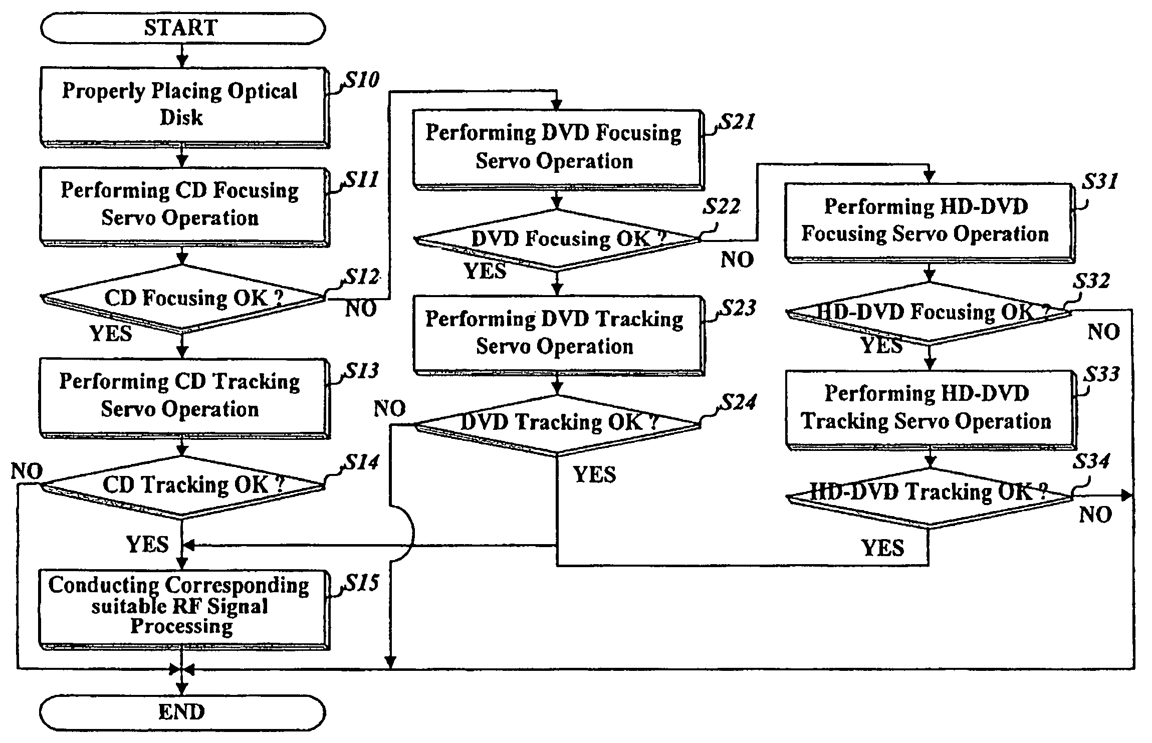
[0021]Now, a servo-controlling method of an optical disk apparatus according to a preferred embodiment of the present invention will be described in detail with reference to the accompanying drawings.

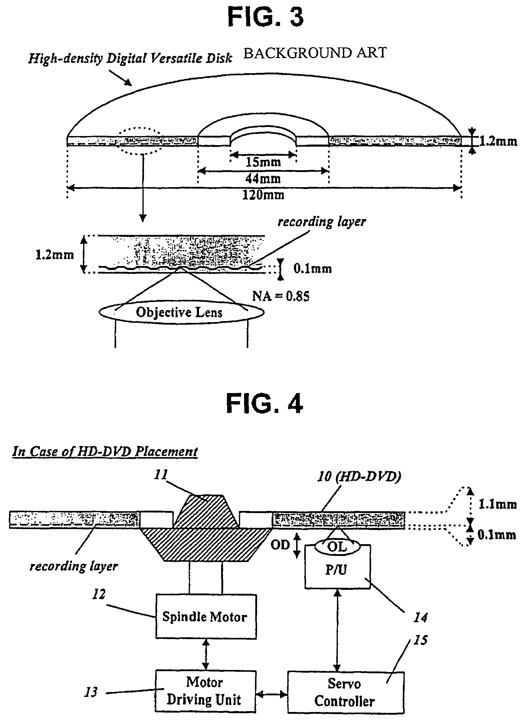
[0022]As previously mentioned with reference to FIGS. 4 and 5, the optical disk apparatus, to which the servo-controlling method of the present invention is applied, basically comprises the turntable 11 on which the optical disk is placed, the spindle motor 12 for rotating the optical disk placed on the turntable 11 at high speed, the motor driving unit 13 for driving the spindle motor 12, the optical pickup 14 for reading signals recorded on the optical disk or recording signals on the optical disk, and the servo controller 15 for controlling the focusing servo operation of moving the object lens OL of the optical pickup 14 vertically relative to the recording layer of the optical disk and the tracking servo operation of moving the object lens OL of the optical pickup 14 horizontally a...


PUM

PropertyMeasurementUnit
light transmittance depthaaaaaaaaaa
diameteraaaaaaaaaa
diameteraaaaaaaaaa

Abstract

The present invention relates to a servo-controlling method of an optical disk apparatus. In the present invention, an order on which servo-control manner is sequentially applied is determined in advance based on various depth to respective recording layers of a CD, a DVD, and a high-density DVD, and when a disk is placed a servo-control manner is sequentially selected in the determined order. Therefore, a collusion between a disk and an optical pickup can be prevented for any type of disk.

Description

1. TECHNICAL FIELD[0001]The present invention relates to a method for controlling a servo operation of an optical disk apparatus depending upon various kinds of optical disks, such as a CD (compact disk), a DVD (digital versatile disk), and a HD-DVD (high-density digital versatile disk).2. BACKGROUND ART[0002]As shown in FIG. 1, a general CD is formed with a thickness of 1.2 mm and a diameter of 120 mm. The CD has a center hole of 15 mm in diameter, and a clamped region of 44 mm in diameter and formed around the center hole. The clamped region is fixed to a turntable of an optical disk apparatus by means of a clamper.[0003]When the CD is properly placed on the optical disk apparatus, a recording layer, on which data are recorded in a pit pattern, is spaced approximately 1.2 mm from the surface of the CD opposite to an object lens of an optical pickup of the optical disk apparatus. The object lens of the optical pickup for the CD has a relatively small numeral aperture (NA). For exam...

Claims


Application Information

Patent Timeline
Patent Type & Authority Patents(United States)
IPC IPC(8): G11B7/00G11B19/12G11B7/004G11B7/085G11B7/09G11B19/02
CPCG11B7/08523G11B7/0945G11B19/12G11B2007/0006G11B7/093G11B7/0938G11B2220/2545G11B2220/2562G11B2220/2579
Inventor PARK, KYUNG CHANKIM, JIN YONG
Owner LG ELECTRONICS INC
Why Eureka
Eureka Blog
Learn More