Microphone system for vehicle

a technology for vehicles and microphones, applied in the direction of piezoelectric/electrostrictive transducers, mouthpiece/microphone attachments, transportation and packaging, etc., can solve the problems of undesired deterioration of the signal to noise ratio of the microphone, difficulty in assembling the accessory to the mirror assembly, etc., to enhance the aesthetic quality or styling of the microphone assembly or system, reduce the effect of turbulen

Inactive Publication Date: 2010-02-02
DONNELLY CORP
View PDF26 Cites 94 Cited by
  • Summary
  • Abstract
  • Description
  • Claims
  • Application Information

AI Technical Summary

Benefits of technology

[0008]The present invention also provides a microphone or microphone assembly or system positioned at or in or partially in an interior rearview mirror assembly of a vehicle or at or in or partially in a windshield electronic module or accessory module of the vehicle. The microphone assembly may include a flow diffusing material or combination of materials which functions to accept and diffuse air flow around the microphone (which may comprise a unidirectional microphone) to minimize the adverse affect of turbulent air flow at or near the microphone, while providing optimal performance and directivity of the microphone.
[0018]The directional microphone may have separated inlet ports for receiving signals from within the vehicle cabin. The mirror system may include an acoustic barrier positioned between the inlet ports of the directional microphone to enhance the directivity of the microphone.
[0024]Therefore, the present invention provides a microphone assembly or system which is operable to substantially diffuse turbulent air flow around the microphone while providing for a directional microphone system. The air flow limiting material or skin material functions to limit the affects of turbulence by creating a buffer zone and maintaining the pressure affects out away from the microphone, while the diffusing material diffuses the air flow that does penetrate the skin material. The air flow limiting material thus substantially reduces the turbulence affects while minimizing the size of the diffusing member, in order to enhance the aesthetic quality or styling of the microphone assembly or system. The acoustic barrier or rib or dividing member functions to delay the diffused sound waves traveling along and through the diffusing material so as to have the waves influence the primary and secondary ports of the microphone at different times, thereby enhancing the directivity of the microphone. The present invention thus may function to substantially physically isolate one side of the microphone from the other via a mechanical baffle or acoustic barrier or wall between the fore and aft ports of the microphone. The microphone, system or assembly of the present invention thus accepts and substantially diffuses turbulent air around the microphone.
[0025]The present invention also provides an improved mounting structure for positioning and mounting an accessory, such as a microphone module, at least partially within the interior rearview mirror assembly. The first portion of the pocket on the mounting plate of the reflective element and the second portion of the pocket on the bezel combine or cooperate to form the pocket for at least partially receiving and retaining the accessory. By forming a portion of the pocket on one part, and forming another portion of the pocket on the other part, the present invention allows the parts (and the pocket) to come together at the right time during the manufacture or assembly of the mirror assembly, when the microphone module or accessory is provided to the mirror assembly. If the pocket were provided on a single component, the microphone module may not be readily installed or inserted therein.

Problems solved by technology

However, it is often difficult to assemble the accessory to the mirror assembly.
Such intense air blowing onto the windshield, and thus generally toward the interior rearview mirror assembly, may lead to undesired deterioration of the signal to noise ratio of the microphone or microphones positioned at or around the interior rearview mirror assembly.

Method used


Image

  • Microphone system for vehicle
  • Microphone system for vehicle
  • Microphone system for vehicle

Examples


Embodiment Construction

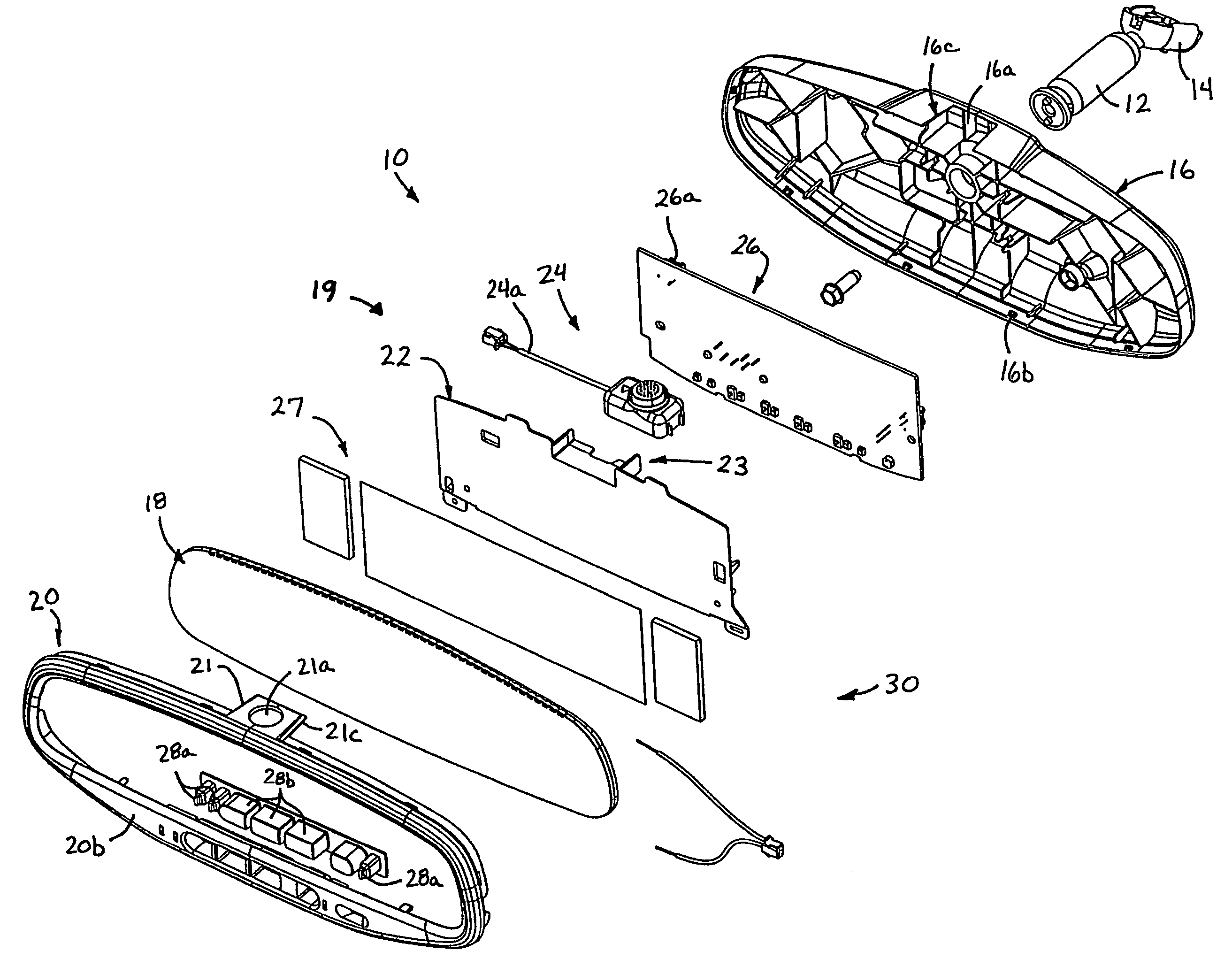
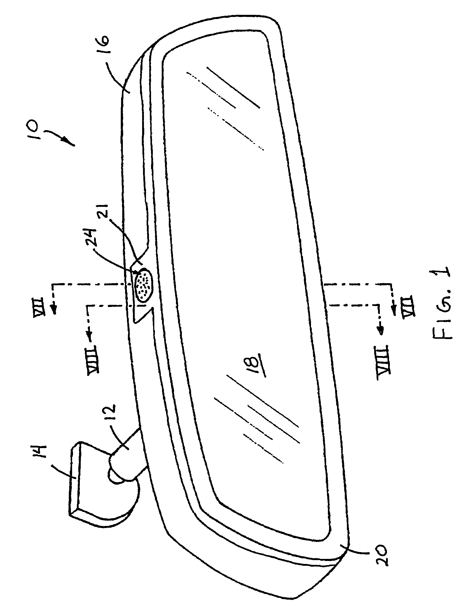
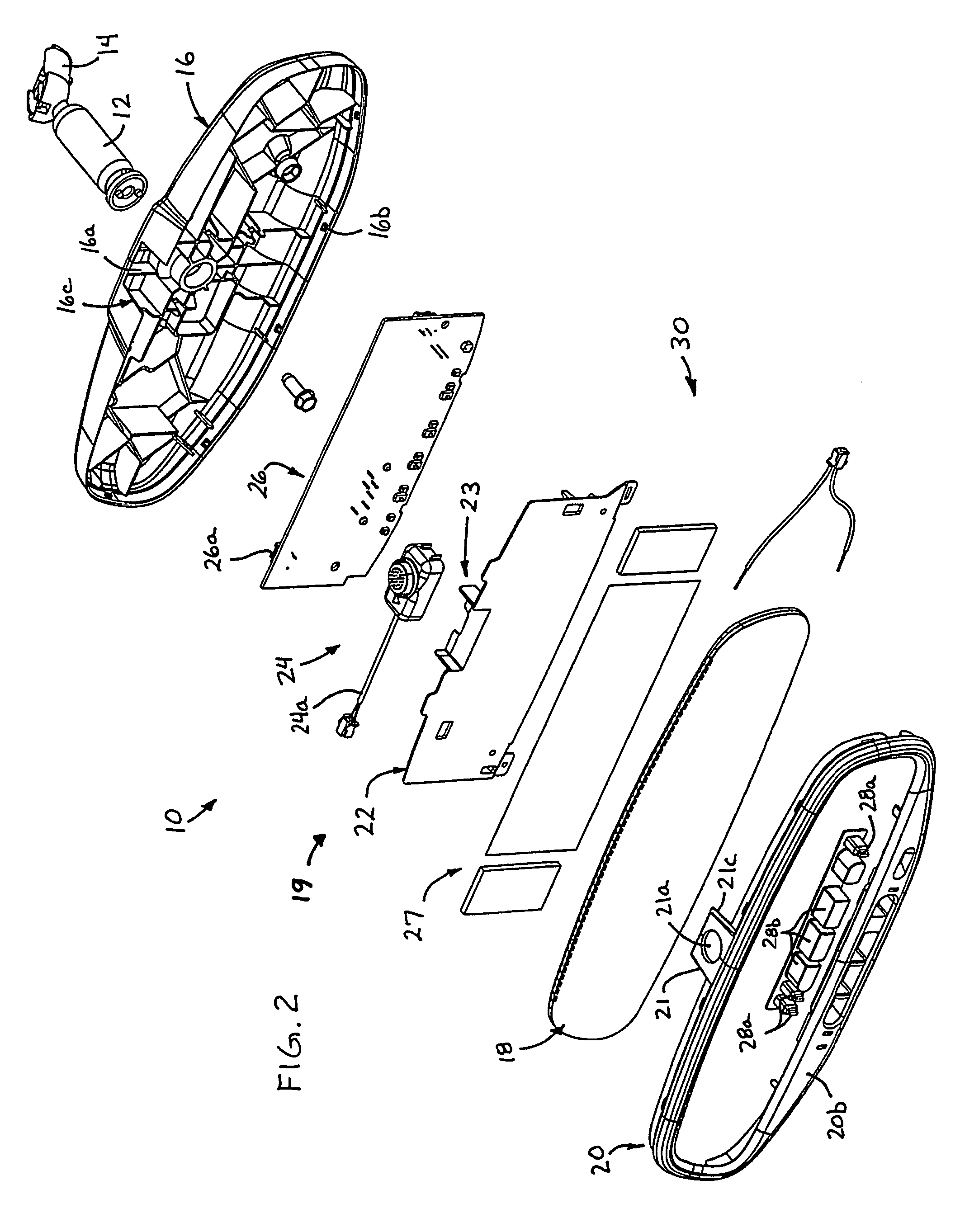
[0049]Referring now to the drawings and the illustrative embodiments depicted therein, an interior rearview mirror assembly 10 is mounted to a mounting arm 12 and mounting base portion 14 (FIGS. 1 and 2), which may be mounted at an interior surface of a windshield of a vehicle (not shown). Mirror assembly 10 includes a housing or casing 16, a reflective element or reflective element assembly or cell 18, and a bezel 20. A mounting plate or attachment plate 22 is positioned on a rear surface 18a (FIGS. 4-10) of reflective element assembly 18 and includes a partial pocket or platform 23 which combines with an accessory tab 21 of bezel 20 to define an accessory pocket for at least partially receiving an accessory 24 therein, as discussed below.

[0050]Accessory 24 may be a microphone module or assembly or the like for receiving audio or voice signals from within the cabin of the vehicle. The microphone module may be part of a voice acquisition system, a telecommunication system, a telemat...


PUM


Abstract

A vehicle interior rearview mirror assembly (10) comprises an accessory (24), a reflective element (18) and a bezel (20). The mirror assembly may define portions of a pocket (23) that at least partially receives and secures the accessory therebetween when the reflective element is at least partially received in the bezel. The mirror assembly (11) may include a microphone (124) and an acoustic cover (126) positioned at least partially over one or more inlet ports (124j, 124k) of the microphone. The acoustic cover may include an outer air flow limiting layer (130b) that substantially limit air flow therethrough and a diffusing material (130a) that may space and support the outer layer from the inlet ports to substantially diffuse air flow that penetrates the outer layer. An acoustic barrier (132) may be positioned between a pair of inlet port of the microphone to enhance the directivity of the microphone.

Description

CROSS REFERENCE TO RELATED APPLICATIONS[0001]The present application is a 371 national phase application of PCT Application No. PCT / US2003 / 030877, filed Oct. 1, 2003, which claims priority of U.S. provisional application Ser. No. 60 / 415,233, filed Oct. 1, 2002 by DeBoer et al. for INTERIOR REARVIEW MIRROR ASSEMBLY WITH ACCESSORY; and Ser. No. 60 / 429,360, filed Nov. 26, 2002 by Weller for MICROPHONE SYSTEM FOR VEHICLE, which are hereby incorporated herein by reference in their entireties.FIELD OF THE INVENTION[0002]The present invention relates generally to a microphone or microphones or microphone system in a vehicle and, more particularly, to a microphone or microphones or microphone system in entities that are positioned in, at or adjacent to an interior rearview mirror assembly of the vehicle and / or a windshield electronic module and / or an accessory module.BACKGROUND OF THE INVENTION[0003]Interior rearview mirror manufacturers typically manufacture and / or purchase various compone...

Claims


Application Information

Patent Timeline
Patent Type & Authority Patents(United States)
IPC IPC(8): H04R25/00B60R1/12H04N7/18H04R1/08H04R1/38
CPCH04N7/18H04R1/083H04R3/00B60R2001/1284H04R1/38H04R2499/13H04R1/086
Inventor LARSON, MARK LWELLER, ANDREW DBARR, JOSHUA LBIGONESS, ERIC PLAMBRIX, TIMOTHY RDEBOER, CAROL LMCCAW, JOSEPH P
Owner DONNELLY CORP
Why Eureka
Try Eureka