Method of using a flexible circuit

a flexible circuit and flexible technology, applied in the direction of printed circuits, printed circuits, printing, etc., can solve the problems of increasing the difficulty of reliably securing flexible circuits around tight bends, and applications that are currently either impractical or not cost-effectiv

Active Publication Date: 2010-02-09
HEWLETT PACKARD DEV CO LP
View PDF21 Cites 74 Cited by
  • Summary
  • Abstract
  • Description
  • Claims
  • Application Information

AI Technical Summary

Problems solved by technology

In addition, the difficulty in reliably securing the flexible circuit around such tight bends increases.
Further, the increase in stress may result in an increase in broken circuit connections or in delamination of various layers leading to degradation due to environmental causes such as corrosion.
The ability to optimize the bending radius of flexible circuits will open up a variety of applications that are currently either impractical or are not cost effective.

Method used


Image

  • Method of using a flexible circuit
  • Method of using a flexible circuit
  • Method of using a flexible circuit

Examples


Embodiment Construction

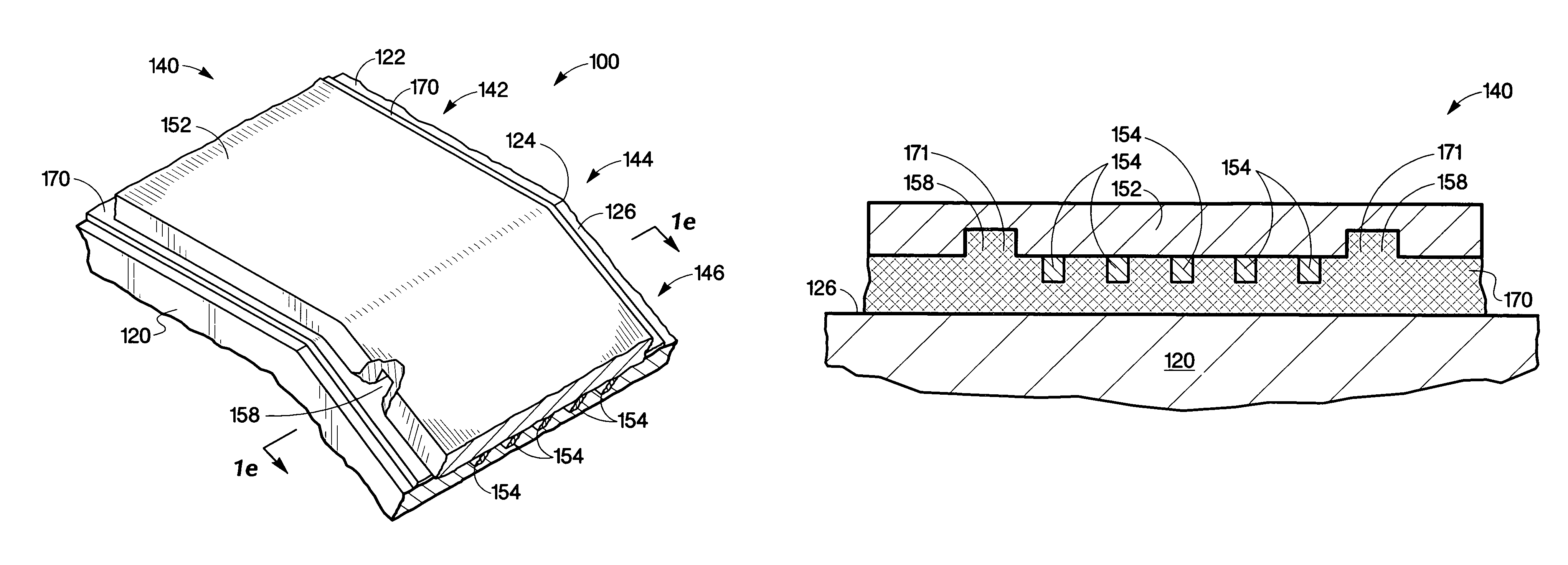
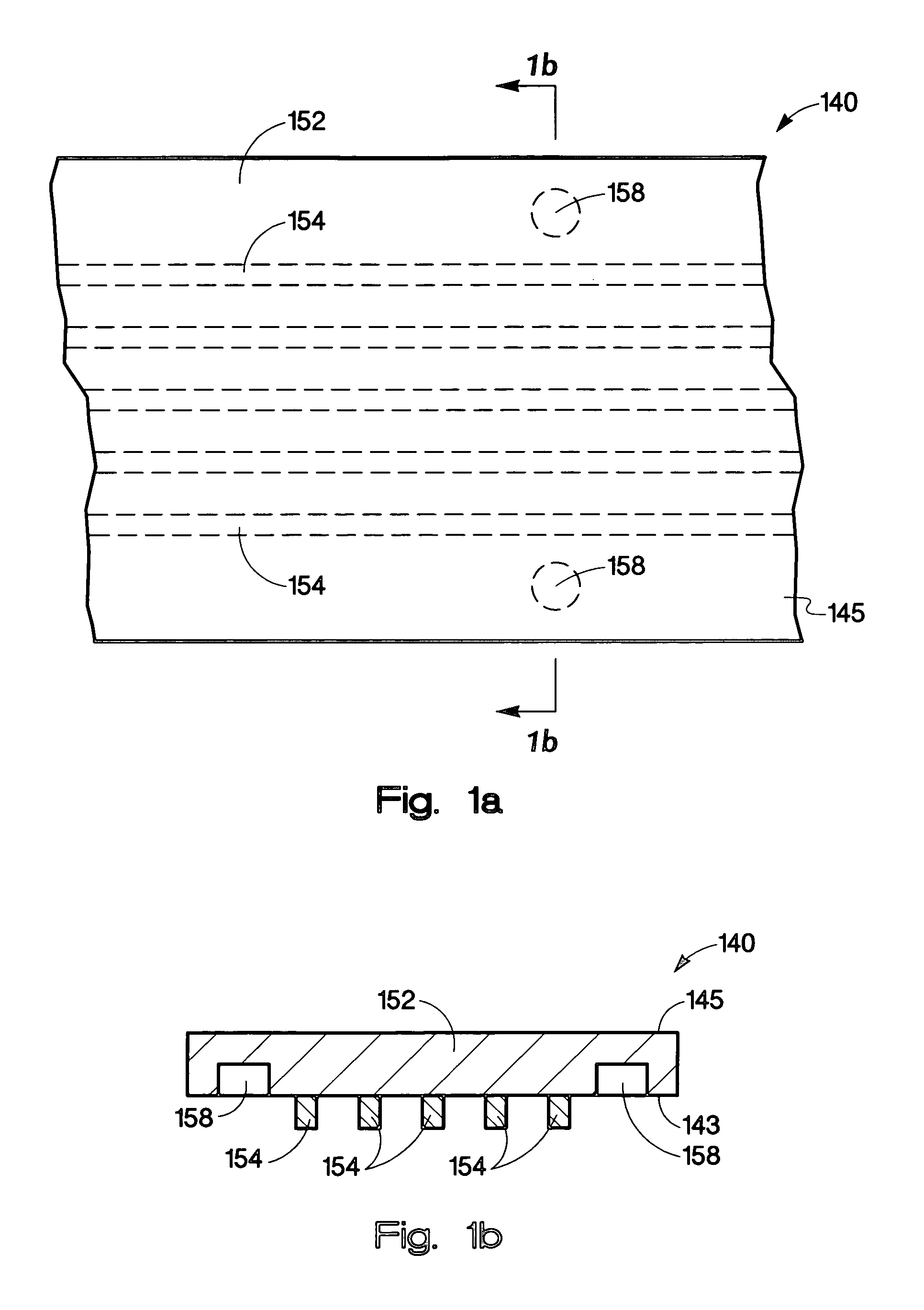
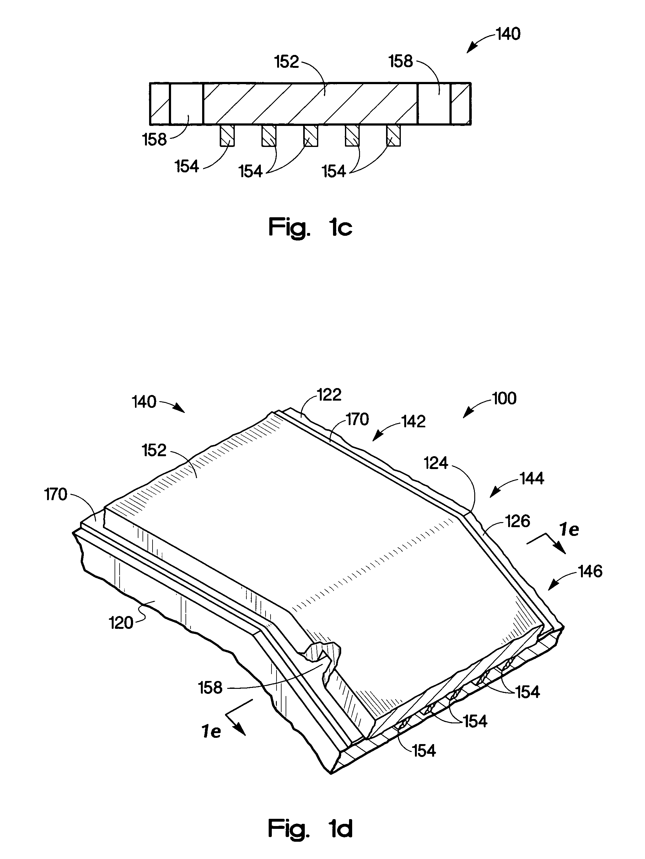
[0026]This invention is directed to utilizing anchor structures created in a flexible circuit to provide a strong adhesive bond in a region of the flexible circuit that is tightly and statically bent or wrapped over an edge of a die carrier. In addition to the adhesive strength of the bond formed between the adhesive and the flexible circuit material, the cleat-like structure provides additional adhesive strength, in the region of the tight static bend, it is believed but not limited by the cohesive strength of the adhesive utilized to form the cleat like structure. A wide variety of anchor structures may be utilized in the present invention such as recessed structures and even through holes through which an adhesive may flow to create a cleat-like structure. The present invention may utilize a wide variety of flexible circuits including both the more conventional flexible circuit structures utilizing an adhesive to bond a metal conductor to a dielectric substrate material and to th...


PUM


Abstract

A method of using a flexible circuit, including attaching a first portion of the flexible circuit, via an attaching surface of the flexible circuit, to a first surface of a chip carrier. Statically bending a bending portion of the flexible circuit around an edge formed at the intersection of the first surface of the chip carrier, and a second surface of the chip carrier. Adhesively attaching a second portion of the flexible circuit, via the attaching surface, to the second surface of the chip carrier, where the second portion of the flexible circuit has at least one first anchor structure formed in the attaching surface, where the at least one first anchor structure is adapted to accept an adhesive.

Description

CROSS REFERENCE TO RELATED APPLICATION[0001]The present application is related to co-pending and commonly assigned patent application Ser. No. 11 / 118,201 filed on the same day herewith Robert Weber, Silam Choy, Cary Addington, and Brian Jones and entitled “Method of Using a Flexible Circuit.”BACKGROUNDDescription of the Art[0002]Over the past few years, the demand for ever cheaper and lighter weight electronic devices, including portable devices, has led to a growing need to manufacture durable, lightweight, and low cost electronic circuits of increasing complexity. Many of these electronic devices utilize flexible circuits to make various electrical interconnections. Electronic packaging designers today are faced with packing flexible circuits into ever smaller spaces or attaching them to smaller parts having complex shapes. As the desire to generate tighter bends in flexible circuits increases the residue stress on the flexible circuit also increases. In addition, the difficulty i...

Claims


Application Information

Patent Timeline
Patent Type & Authority Patents(United States)
IPC IPC(8): B41J2/14B41J2/05B41J2/175
CPCB41J2/14072B41J2/17526H05K3/0058H05K3/386H05K2201/09036H05K2201/09063H05K2201/2072
Inventor JONES, BRIANWEBER, ROBERTADDINGTON, CARY GCHOY, SI-LAM
Owner HEWLETT PACKARD DEV CO LP
Why Eureka
Try Eureka