Terminating spatial partition hierarchies by a priori bounding memory

a spatial partition and memory technology, applied in the field of terminating, can solve the problems of slow setup of acceleration data structures, limited ability to process dynamic scenes, and known limitations and weaknesses of current ray tracing techniques

Inactive Publication Date: 2010-02-09
MENTAL IMAGES
View PDF18 Cites 44 Cited by
  • Summary
  • Abstract
  • Description
  • Claims
  • Application Information

AI Technical Summary

Benefits of technology

[0024]such that depth is implicitly controlled by the scheduled memory, and the scheduling allows local adaptation of depth.
[0043]Yet another aspect of the invention comprises maximizing frame rate by measuring a total time to image and then dynamically adjusting the size of the provided memory block from frame to frame as necessary.
[0045]Still another aspect of the invention comprises reducing page thrashing by storing the upper part of the inner nodes of the spatial hierarchy in a part of memory that permanently remains in main memory, and wherein the objects in a top level tree can be trees themselves that can be flushed to disk and rebuilt or generated on demand.
[0059]such that depth is implicitly controlled by the scheduled memory, and the scheduling allows local adaptation of depth.
[0061]computer program code means, the first computer program code means comprising computer-readable instructions executable within the computer graphics system for utilizing a termination criterion and memory scheduling heuristic to enable construction of an efficient ray tracing acceleration data tree structure in a given, a priori fixed memory block, the termination criterion and memory scheduling heuristic comprising: (A) transmitting, for use in constructing the acceleration data tree structure, a contiguous portion of memory along with a value representative of the size of the contiguous portion of memory, and instead of terminating the hierarchy by controlling a maximum depth of the tree, constructing a leaf node, if two reference lists resulting from a classification step plus the size of a tree node do not fit into the given memory block; and (B) predicting the memory consumption of the two new sub-trees in the sorting and accordingly distributing the available memory to the left and right children when continuing recursively, the predicting comprising computing a prediction pε[0, 1], which schedules a fraction of memory scheduled for the left child, the remainder of the memory being scheduled for the right child, such that depth is implicitly controlled by the scheduled memory, and the scheduling allows local adaptation of depth.

Problems solved by technology

However, current ray tracing techniques suffer from a number of known limitations and weaknesses, including numerical problems, limited capabilities to process dynamic scenes, slow setup of acceleration data structures, and large memory footprints.
Thus, current ray tracing techniques lack the capability to deal efficiently with fully animated scenes, such as wind blowing through a forest or a person's hair.
Current attempts to improve the performance of ray tracing systems have fallen short for a number of reasons.
Because the main focus of these systems is on rendering static scenes, they typically fail to address the significant amount of setup time required to construct the required data structures in connection with fully animated scenes.
However, it has been found that the architecture's performance breaks down if too many incoherent secondary rays are traced.
The construction of acceleration structures has not yet been implemented in hardware.
Aside from various existing heuristics, memory management is substantially always an issue.
While hierarchically partitioning the list of objects allows one to predict the memory footprint, these techniques based on bounding volumes can suffer from inefficiencies caused by large objects and the convexity of the applied bounding volumes.

Method used


Image

  • Terminating spatial partition hierarchies by a priori bounding memory
  • Terminating spatial partition hierarchies by a priori bounding memory
  • Terminating spatial partition hierarchies by a priori bounding memory

Examples


Embodiment Construction

Digital Processing Environment in which Invention can be Implemented

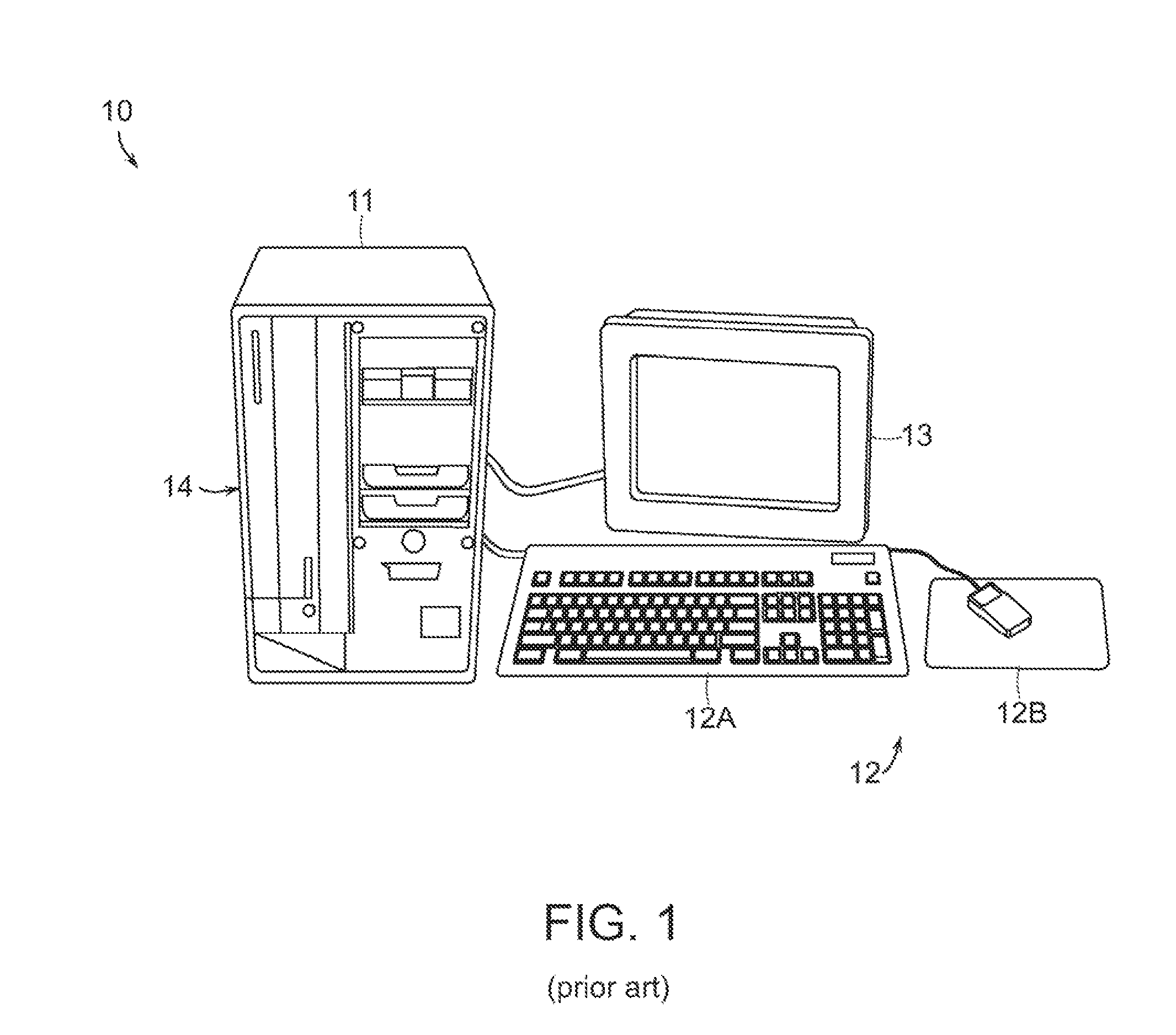
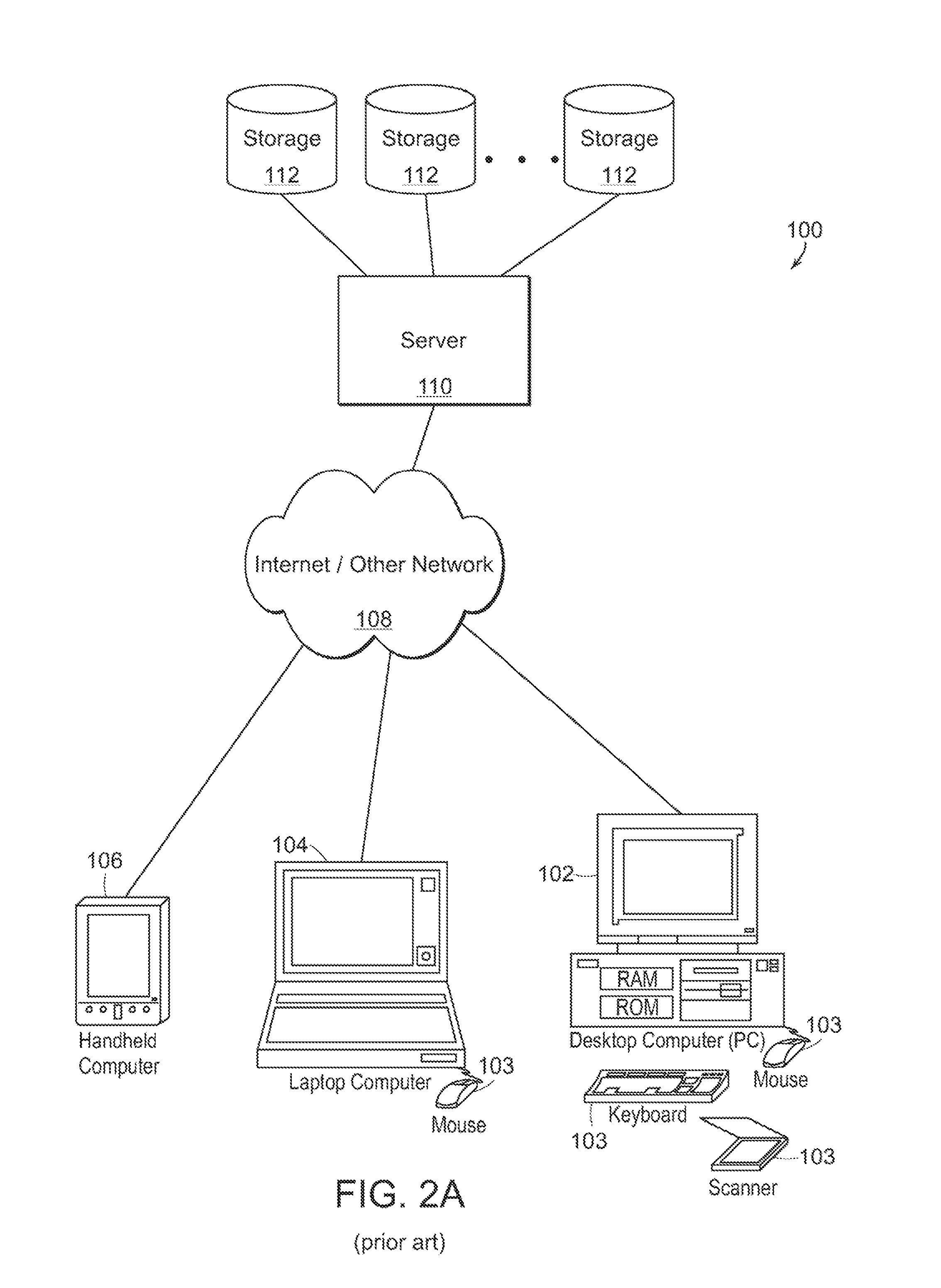
[0103]Before describing particular examples and embodiments of the invention, the following is a discussion, to be read in connection with FIGS. 1 and 2, of underlying digital processing structures and environments in which the invention may be implemented and practiced.

[0104]It will be understood by those skilled in the art that the present invention provides methods, systems, devices and computer program products that enable more efficient ray tracing and other activities in computer graphics systems, whose output is typically a human-perceptible (or digitally stored and / or transmitted) image or series of images that can comprise, for example, an animated motion picture, computer aided design representation, or other typical computer graphics output. The present invention can thus be implemented as part of the computer software or computer hardware of a computer that forms part of a computer graphics system, along...


PUM


Abstract

The present invention provides methods, systems and computer program code (software) products for terminating spatial partition hierarchies and other hierarchies by a priori bounding.

Description

CROSS-REFERENCE TO RELATED APPLICATIONS[0001]This application for patent claims the priority benefit of U.S. Provisional Patent Application Ser. Nos. 60 / 886,197 and 60 / 910,940, filed respectively on Jan. 23, 2007, and Apr. 10, 2007.[0002]The present application is a Continuation-in-Part of U.S. patent application Ser. No. 11 / 737,424, filed on Apr. 19, 2007, which claims the priority benefit of U.S. Provisional Patent Application Ser. No. 60 / 793,063, filed on Apr. 19, 2006.[0003]U.S. patent application Ser. No. 11 / 737,424 is in turn a Continuation-In-Part of U.S. patent application Ser. No. 11 / 474,517, entitled “Real-Time Precision Ray Tracing”), filed Jun. 23, 2006.[0004]U.S. patent application Ser. No. 11 / 474,517 claims the priority benefit of U.S. Provisional Patent Application Ser. No. 60 / 693,231, filed Jun. 23, 2005, and is in turn a Continuation-In-Part of U.S. patent application Ser. No. 10 / 299,574, filed Nov. 19, 2002.[0005]U.S. patent application Ser. No. 10 / 299,574 is in tu...

Claims


Application Information

Patent Timeline
Patent Type & Authority Patents(United States)
IPC IPC(8): G06T15/50G06F17/00
CPCG06T1/60G06T15/06G06T15/40
Inventor KELLER, ALEXANDERWAECHTER, CARSTEN
Owner MENTAL IMAGES
Why Eureka
Try Eureka