Method and apparatus for improved data acquisition using a solid state digital X-ray detector

a digital x-ray detector and data acquisition technology, applied in the field of xray imaging, can solve the problems of inconvenient production of complex detectors, affecting the image quality of images, and internal defects of objects, and achieve the effect of maximizing frame rate and minimizing read out tim

Active Publication Date: 2006-11-07
GENERAL ELECTRIC CO
View PDF5 Cites 6 Cited by
  • Summary
  • Abstract
  • Description
  • Claims
  • Application Information

AI Technical Summary

Benefits of technology

[0020]The method may also include defining a region of interest in the detector. The pixels obtain image data regarding the region of interest. Additionally, the method may include reading the image data from at least one scan line in each of the groups of scan lines using the associated data lines. Alternatively, the method may include reading the image data from alternating groups of the scan lines using the associated data lines. The method may include binning image data from adjacent pixels read using a plurality of data lines. In an embodiment, one reading is obtained per group at any given time during reading the detector, so as to minimize the read out time (maximize the frame rate).

Problems solved by technology

For instance, internal defects in an object may be detected.
Lack of switching elements may make the production of complex detectors prohibitive.
Furthermore, electronic noise affecting an image may be influenced by the resistance and capacitance of data lines reading out data from the detector array.
However, the read out electronics with split data lines may operate at only half the speed of read out electronics with unsplit data lines to achieve the same detector read out rate.
Thus, less demanding or different applications suffer from inefficient performance.
For vascular imaging, data modules may consume more power than for other applications, such as chest radiography.
Custom integrated circuits involve significant time to develop and to improve.

Method used


Image

  • Method and apparatus for improved data acquisition using a solid state digital X-ray detector
  • Method and apparatus for improved data acquisition using a solid state digital X-ray detector
  • Method and apparatus for improved data acquisition using a solid state digital X-ray detector

Examples


Embodiment Construction

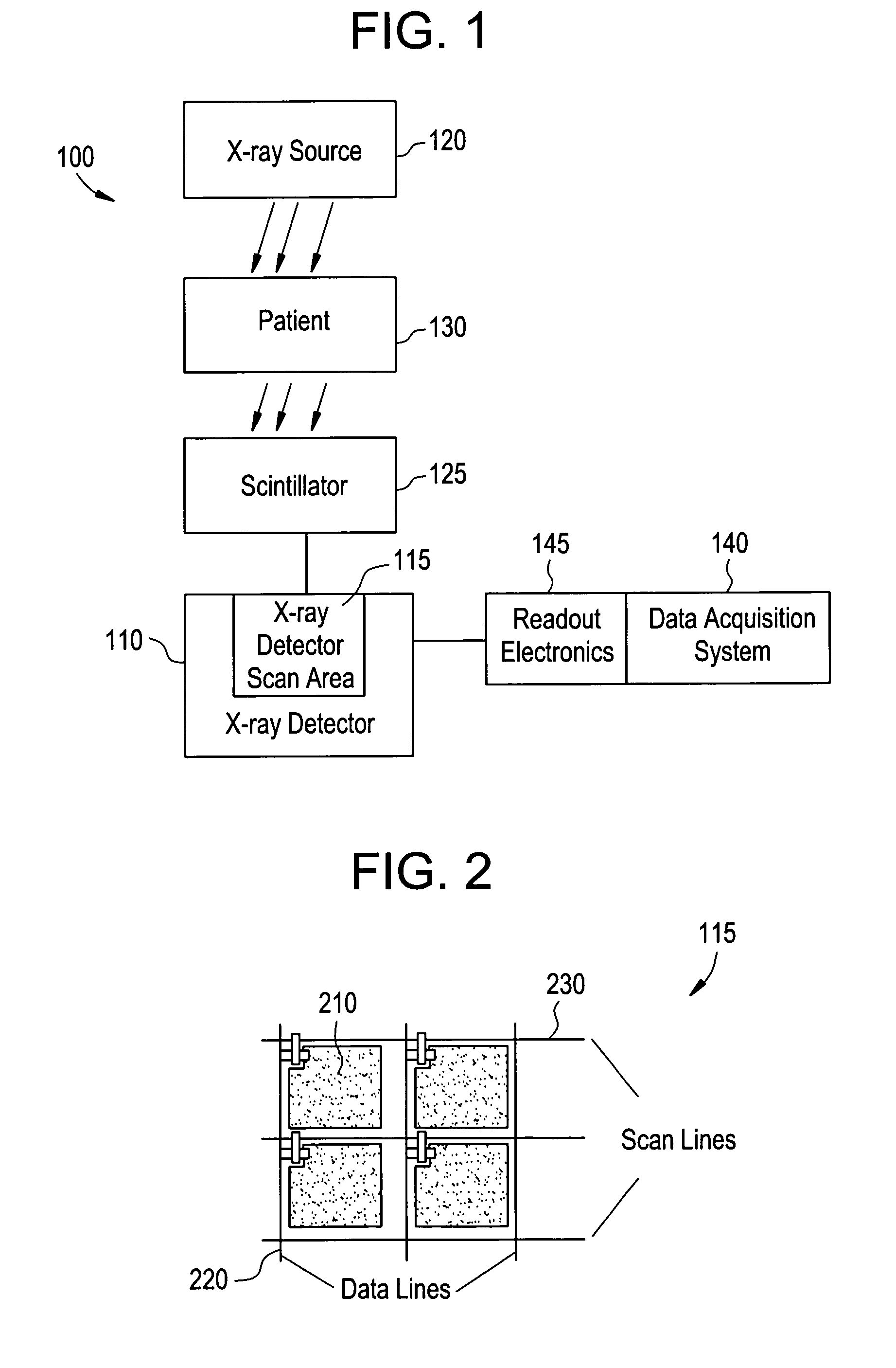
[0035]FIG. 1 illustrates an imaging system 100 used in accordance with an embodiment of the present invention. The imaging system 100 includes a plurality of subsystems. For the purposes of illustration, the imaging system 100 is described as an x-ray system. The imaging system 100 includes subsystems, such as an x-ray detector 110 including an array 115 of detector cells, an x-ray source 120, a scintillator 125, and an object 130. The imaging system 100 also includes a data acquisition system 140 with read out electronics 145. In an embodiment, the scintillator 125 comprises a screen positioned in front of the detector 110. In an embodiment, the detector 110 is an amorphous silicon flat panel detector. The object 130 may be a patient or another object to be imaged.

[0036]The object 130 is positioned in imaging system 100 for imaging. In one exemplary system, an x-ray source 120 is positioned above the object 130. The x-ray detector 110 is positioned below the object 130. The scintil...


PUM

PropertyMeasurementUnit
timeaaaaaaaaaa
interface rateaaaaaaaaaa
internal structureaaaaaaaaaa

Abstract

Certain embodiments provide a method and system for improved x-ray image data acquisition using a digital x-ray detector. The method and system include defining groups of scan lines in a detector, associating data lines in the detector with the groups of scan lines, and reading image data from the groups of scan lines using the associated data lines. The scan lines are connected with a plurality of pixels. A region of interest may be defined in the detector. The pixels obtain image data regarding the region of interest. The image data may be read from at least one scan line in each of the groups of scan lines using the associated data lines. Alternatively, the image data may be read from alternating groups of the scan lines using the associated data lines. Image data may also be binned from adjacent pixels read using a plurality of data lines.

Description

RELATED APPLICATIONS[0001]The present application relates to, and claims priority from, U.S. Provisional Application No. 60 / 543,762 filed on Feb. 11, 2004, and entitled “Method and Apparatus for Improved Data Acquisition Using a Solid State Digital X-ray Detector”.FEDERALLY SPONSORED RESEARCH OR DEVELOPMENT[0002][Not Applicable]MICROFICHE / COPYRIGHT REFERENCE[0003][Not Applicable]BACKGROUND OF THE INVENTION[0004]The present invention generally relates to x-ray imaging. In particular, the present invention relates to improved x-ray image data acquisition using a digital x-ray detector.[0005]X-ray images may be used for many purposes. For instance, internal defects in an object may be detected. Additionally, changes in internal structure or alignment may be determined. Furthermore, the image may show the presence or absence of internal structures in the object. The information gained from x-ray imaging has applications in many fields, including medicine and manufacturing.[0006]X-ray im...

Claims


Application Information

Patent Timeline
Patent Type & Authority Patents(United States)
IPC IPC(8): G01T1/24G01T1/20A61B6/00G01J1/00G01N23/04G01T1/29H01L27/14H01L27/146H04N5/32H04N5/345H04N5/369
CPCH01L27/14658H04N3/1593H04N5/32H04N25/41
Inventor PETRICK, SCOTT WILLIAMBLOMEYER, ALAN DEANLIANG, JINGYICRONCE, RICHARD GORDON
Owner GENERAL ELECTRIC CO
Why Eureka
Try Eureka