Orbital tube welding clamping fixture support

a technology of clamping fixture and orbital tube, which is applied in the direction of soldering apparatus, manufacturing tools,auxillary welding devices, etc., can solve the problems of severe weld degradation, reduced overall strength, and increased compactness, so as to facilitate opening and closing, prevent mechanical interference, and minimize clearance

Inactive Publication Date: 2010-02-16
ORBITAL ACQUISITION
View PDF5 Cites 21 Cited by
  • Summary
  • Abstract
  • Description
  • Claims
  • Application Information

AI Technical Summary

Benefits of technology

[0024]To facilitate the opening and closure of both the right top side and left top side, in any sequence, a clearance is provided between the right engagement face and the left engagement face. Additionally, the length and width of the engaging leg is less than the length and width of the engagement notch, respectively. This allows the engagement leg of one clasp to clear the engagement notch of the opposing clasp, as one top side is swiveled about its hinge, to the open position.
[0025]In one possible usage scenario of the present invention, a new tube is designated to be welded to an existing tube extending from a complex assembly. The right side of the clamping means, with the right clasp attached, is clamped to the existing tube, and locked in the closed position by the latch. The new tube is prepared, and then inserted into the left side of the clamping means, with the left clasp attached. The position and geometry of the identical, but inverted clasps provide for ample clearance to allow the opening or closure of either side in any sequence. The clearance between the right engagement face and the left engagement face is sufficient to prevent mechanical interference during opening and closure; however, that clearance is minimized to prevent outward flexure of both top sides of the clamping means.
[0026]The clasp of the present invention can also be constructed with the engaging leg and the mounting leg having substantially the same length. In order for the engaging leg of one clasp to engage with the...

Problems solved by technology

The thickness of the clamping means, as well as the overall dimensions, are often minimized, increasing compactness, but reducing overall strength.
On average, a gap of less 10% of the wall thickness can cause severe weld degradation.
The clamping means described previously allows for slight, but unacceptable, movement of the tubes during welding, because of its light construction.
The hinges and clamping mechanisms fastening the top sides to the bottom sides cannot effectively prevent this skewing.
The resulting gap can degrade the weld, or cause it to fail completely.
An unacceptably wide gap in the seam can result in an uneven weld bead, having less parent material in that general area, or a an actual hole or permanent gap can be formed in the resulting cured weld bead.
It can also result in a blowout of the weld, if an internal purge is utilized.
All of these conditions, as well as others, can cause a weld to be rejected by quality control, costing an unacceptable loss in time and money.
These designs, although...

Method used


Image

  • Orbital tube welding clamping fixture support
  • Orbital tube welding clamping fixture support
  • Orbital tube welding clamping fixture support

Examples


Embodiment Construction

[0036]The detailed description set forth below in connection with the appended drawings is intended as a description of presently-preferred embodiments of the invention and is not intended to represent the only forms in which the present invention may be constructed and / or utilized. The description sets forth the functions and the sequence of steps for constructing and operating the invention in connection with the illustrated embodiments. However, it is to be understood that the same or equivalent functions and sequences may be accomplished by different embodiments that are also intended to be encompassed within the spirit and scope of the invention.

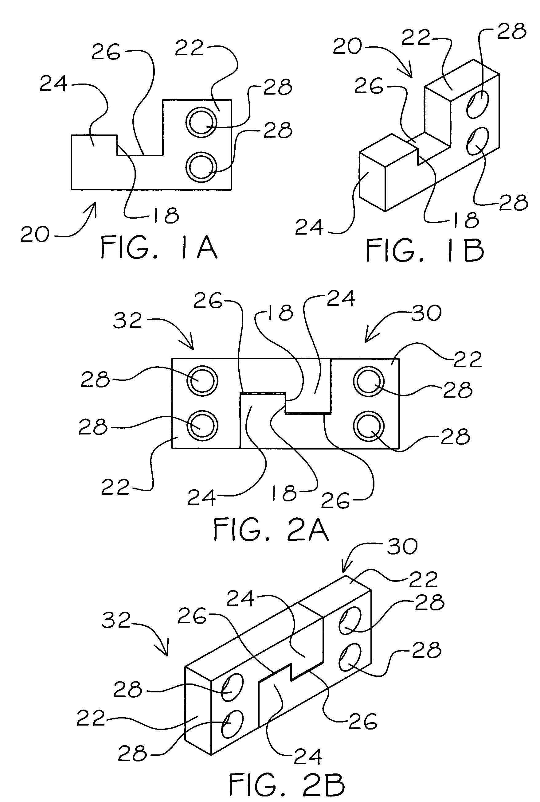
[0037]The clasp (20) of the present invention can be seen in FIGS. 1A and 1B. Looking more particularly at FIG. 1A, it can be seen that, generally, from the front face, the shape of the clasp (20) is a square cornered J-shape. The clasp (20) in comprised of two legs, the mounting leg (22) and the engaging leg (24), and an engaging notch...


PUM


Abstract

A clamping means support for use with orbital tube welding that resists the outward flexure of abutting tubes is provided. The invention generally is comprised of a left clasp and a right clasp, being congruent. The right clasp is generally square cornered J-shaped, having a mounting leg, and an engaging leg, an engagement notch formed between the long leg and the short leg. The right clasp is fastened upright, at the mounting leg, to a right top side of a clamping means. The left clasp is fastened invertible, at the mounting leg, to a left top side of a clamping means. Wherein, in the closed position, the engagement leg of the right clasp interlocks within the engagement notch of the left clasp, effectively preventing outward movement of the right top side and the left top side of the clamping means, relative one to the other.

Description

FIELD OF THE INVENTION[0001]This invention relates generally to a clamping means for welding together metal tubular components and method for use thereof, and, more particularly, to a device that prevents flexure and separation of the clamping means and the tubular components affixed thereto, due to component weight stresses and welding induced forces.BACKGROUND OF THE INVENTION[0002]In high purity applications, it is common to use an orbital welding device, such as the device disclosed in U.S. Pat. No. 5,196,664 to McGushion (1993), to butt-weld together two components with annular cross sections, held together end to end by a clamping means. The components could include pipes, tubes, or tubular extensions protruding from components, such as regulators, valves, mass flow controllers / meters, or a wide variety of other similar components with a tube-like extension. Tube is used interchangeably for any of the above mentioned components.[0003]The clamping means has primarily two sides,...

Claims


Application Information

Patent Timeline
IPC IPC(8): B23K1/18
CPCB23K37/0533
Inventor MCGUSHION, KEVIN DAVID
Owner ORBITAL ACQUISITION
Why Eureka
Try Eureka