Shredder

a shredder and article technology, applied in the field of shredders, can solve the problems of affecting the shredding effect, the shredding machine has a usage problem or even a breakdown, and the thick article is easily jammed, so as to avoid the trembling of the shredding article during the shredding operation

Inactive Publication Date: 2010-02-16
PRIMAX ELECTRONICS LTD
View PDF3 Cites 16 Cited by
  • Summary
  • Abstract
  • Description
  • Claims
  • Application Information

AI Technical Summary

Benefits of technology

[0010]It is an object of the present invention to provide a shredder capable of avoiding the trembling of the shredding article during the shredding operation.
[0011]In accordance with a first aspect of the present invention, there is provided a shredder. The shredder includes a shredding mechanism, a movable element and a sustaining mechanism. The shredding mechanism includes an entrance, a shredding path, a first driving assembly, a second driving assembly, a sensing assembly and a shredding knife assembly. The sensing assembly is electrically connected to the first and second driving assemblies. The entrance is disposed at a top side of the shredding mechanism for feeding an article to be shredded therethrough. The shredding path is arranged between the entrance and the shredding knife assembly. The movable element is disposed under the entrance and arranged at a lateral side of the shredding path. The article is introduced into the shredding path through the entrance to be sustained against the movable element such that the movable element is shifted to result in a shift distance with respect to its original place. The sustaining mechanism is arranged at the lateral side of the shredding path to be sustained against the article passing through the shredding path, thereby reducing the trembling degree of the article when a shredding operation is implemented on the article and maintaining the shift distance less than a threshold value. An enable signal is issued from the sensing assembly when the shift distance of the movable element is less than the threshold value. In response to the enable signal, the first driving assembly is activated to have the shredding knife assembly perform the shredding operation and the second driving assembly is activated to have the sustaining mechanism move from an initial position to a sustaining position to be sustained against the article.
[0013]In accordance with a third aspect of the present invention, there is provided a shredder. The shredder includes an entrance, a shredding knife assembly, a shredding path, a driving assembly, a movable element, a pusher element and a sensing assembly. The shredding path is arranged between the entrance and the shredding knife assembly. The driving assembly is used for driving the shredding knife assembly coupled thereto, so that an article is introduced into the shredding path through the entrance to be shredded by the shredding knife assembly. The movable element is disposed under the entrance and arranged at a lateral side of the shredding path. The article is introduced into the shredding path through the entrance to be sustained against the movable element such that the movable element is shifted to result in a shift distance with respect to its original place. The pusher element is coupled to the driving assembly and disposed in the vicinity of the movable element. The press element is disposed beside the pusher element and synchronously moved with the pusher element. The sensing assembly is electrically connected to the driving assembly. An enable signal is issued from the sensing assembly when the shift distance of the movable element is less than a threshold value. In response to the enable signal, the driving assembly is activated to have the shredding knife assembly perform a shredding operation and have the sustaining mechanism move from an initial position to a sustaining position to be sustained against the article, thereby reducing the trembling degree of the article when the shredding operation is implemented on the article and maintaining the shift distance less than the threshold value.

Problems solved by technology

If a relatively thick article whose thickness is beyond an acceptable range, for example a thick paper or a compact disc, is shredded, the thick article is readily jammed.
Under this circumstance, the shredder has a usage problem or even a breakdown.
However, this shredder 100 still has some drawbacks.

Method used


Image

  • Shredder
  • Shredder
  • Shredder

Examples


Embodiment Construction

[0020]For avoiding the trembling of the shredded article during the shredding operation, the shredder of the present invention further includes a sustaining mechanism in the vicinity of the movable element. The sustaining mechanism includes a pusher element and a press element. The locations of the pusher element and the press element are varied depending on the manufactures' design. Since the sustaining mechanism is sustained against the shredding article, the influence of the shredding article on the movable element is reduced and the possibility of erroneous interruption of the shredder is reduced.

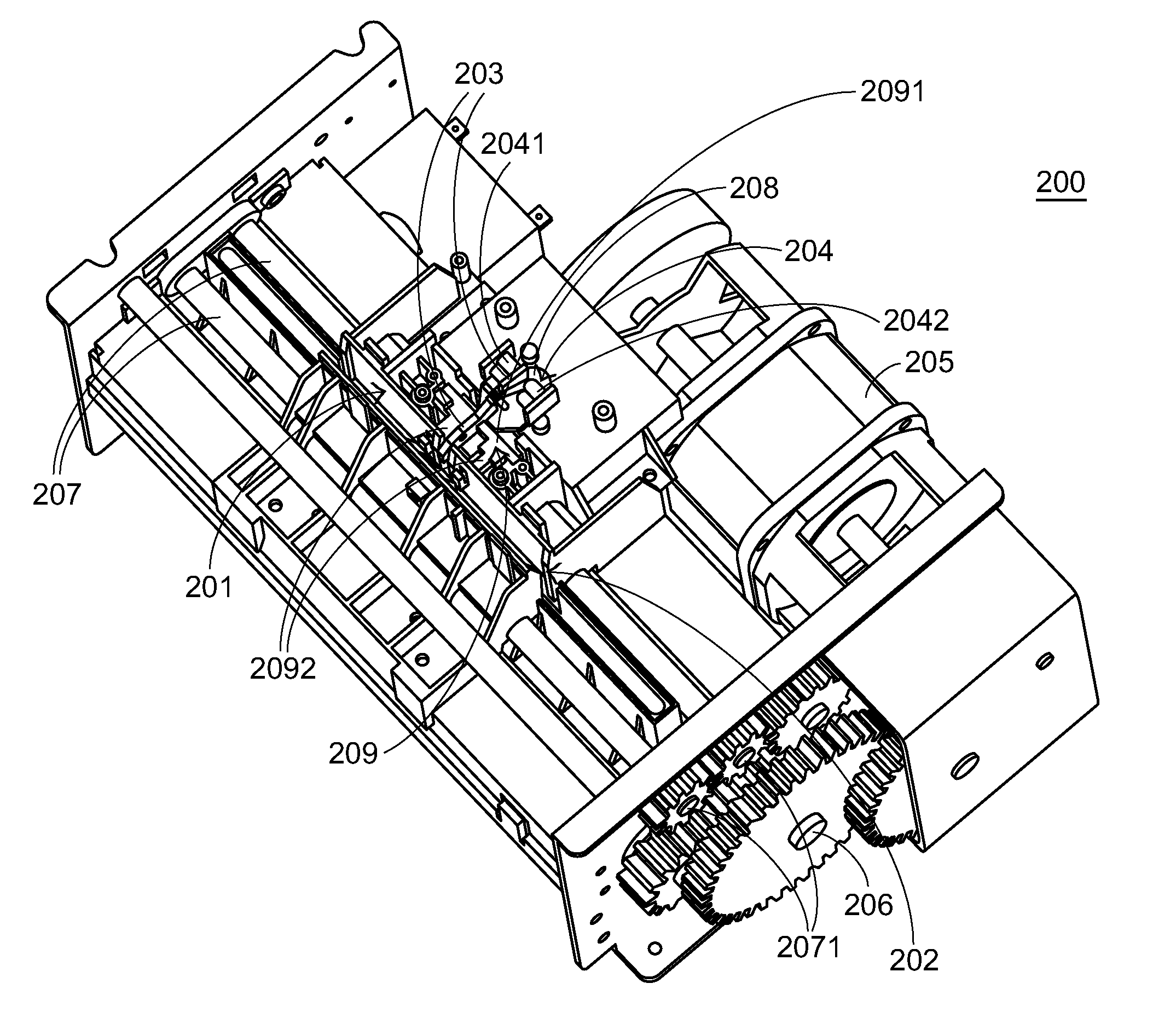
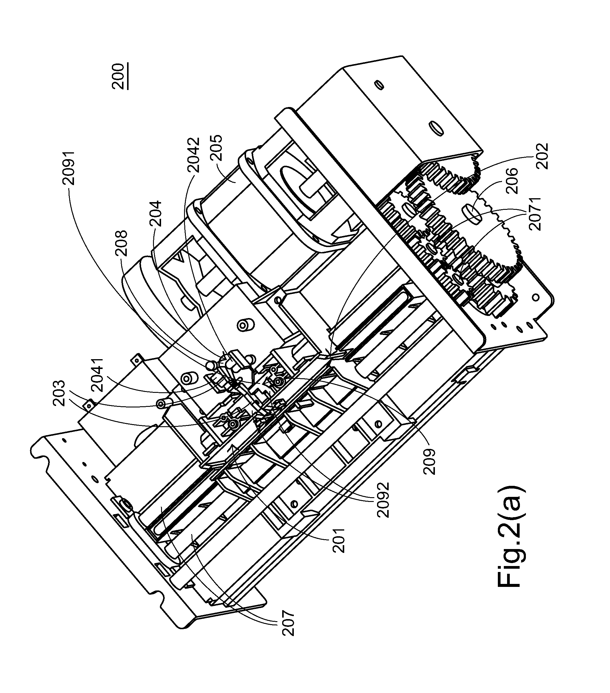
[0021]Please refer to FIGS. 2(a), 2(b), 2(c) and 2(d), which schematically illustrate a shredder according to a preferred embodiment of the invention taken from different directions. The shredder 200 includes an entrance 201, a shredding path 202, a movable element 203, a thickness sensing module 204, a first motor assembly 205, a transmission gear set 206, an eccentric cam 208, a push ...


PUM


Abstract

The present invention relates to a shredder having a thickness triggering device. During the shredding operation, the trembling of the article is minimized or eliminated by using the shredder. The shredder includes a sustaining mechanism and a driving assembly. Since the sustaining mechanism is sustained against the shredding article, the amplitude of the trembling article is largely reduced. As a consequence, the influence of the shredding article on the thickness triggering device is reduced so as to prevent interruption of the shredder.

Description

FIELD OF THE INVENTION[0001]The present invention relates to a shredder, and more particularly to a shredder having a thickness triggering device.BACKGROUND OF THE INVENTION[0002]Nowadays, shredders are used to cut articles. If a relatively thick article whose thickness is beyond an acceptable range, for example a thick paper or a compact disc, is shredded, the thick article is readily jammed. Under this circumstance, the shredder has a usage problem or even a breakdown. For avoiding the occurrence of jamming, a thickness triggering device is mounted in the shredder to determine whether the article to be shredded is beyond the acceptable range.[0003]Referring to FIG. 1, a schematic perspective view of a shredder having a thickness triggering device is illustrated. The shredder 100 includes an entrance 101, a shredding path 102, a movable element 103, a thickness sensing module 104, a driving assembly 105, a transmission gear set 106 and a shredding knife assembly 107.[0004]The entra...

Claims


Application Information

Patent Timeline
Patent Type & Authority Patents(United States)
IPC IPC(8): B02C4/32B02C11/08B02C7/14B02C9/04
CPCB02C18/0007B02C2018/164B02C2018/0038B02C18/06B02C18/2225B02C25/00
Inventor LEE, PEI-YUANLIN, SHIN-FU
Owner PRIMAX ELECTRONICS LTD
Why Eureka
Try Eureka