Rolling process method for nuclear power station nuclear main pump long shaft sleeve

A process method and technology of nuclear main pump, applied in nuclear engineering, nuclear power generation, presses, etc., can solve the problems of cost loss, deformation of the long shaft sleeve of the mandrel, scrapped workpiece, etc., and achieve increased service life, hardness and strength. , the effect of improving wear resistance

Active Publication Date: 2020-11-13
HARBIN ELECTRIC POWER EQUIP
View PDF6 Cites 2 Cited by
  • Summary
  • Abstract
  • Description
  • Claims
  • Application Information

AI Technical Summary

Problems solved by technology

The traditional process method is that the fixed end caps at both ends of the long bushing are penetrated into the mandrel and rolled on a horizontal lathe. The defect is that this method will cause deformation of the long bushing. The inner and outer circle runout of the long shaft sleeve is 0.02mm, the coaxiality is 0.01mm, and the wall is thin, the thinnest part is only 13mm, and the length is 1100mm. It is easy to deform during the rolling process. The traditional process method adopts horizontal For rolling, it is necessary to use the chuck of the machine tool to clamp one side of the end cover, and the tip is to withstand the mandrel on the other side. It is difficult to control the size of the tip force. Small size will cause the pressure generated during rolling to change the radial position of the long bushing, which cannot guarantee the success of rolling, and the thin-walled long bushing will be deformed

Method used


Image

  • Rolling process method for nuclear power station nuclear main pump long shaft sleeve
  • Rolling process method for nuclear power station nuclear main pump long shaft sleeve

Examples


Embodiment Construction

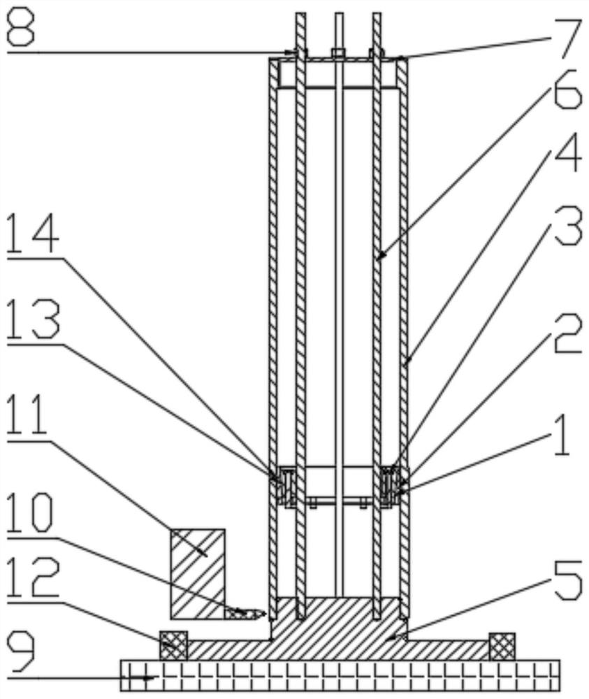
[0023] A rolling process method for a long shaft sleeve of a nuclear main pump of a nuclear power plant, comprising the following steps:

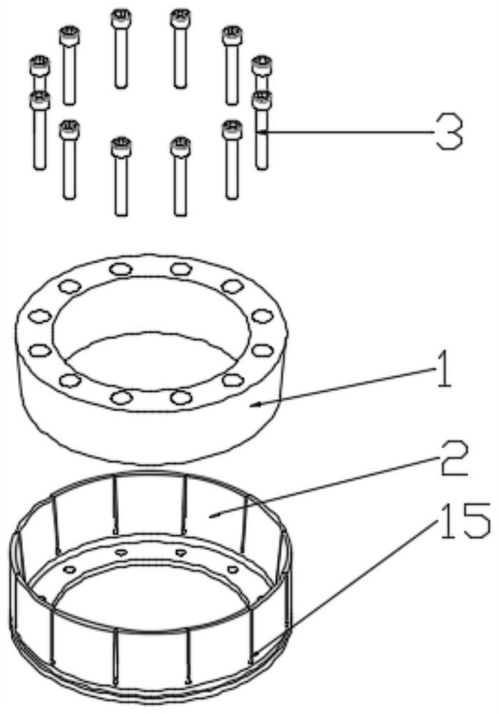
[0024] 1) The inner support 1 and the outer support 2 are assembled together by bolts 3 and installed on the inner hole step 14 of the long shaft sleeve 4, such as figure 1 As shown, through the clockwise rotation of the bolt 3, the inner support 1 slides on the contacting slope 13 to the bottom surface of the outer support 2, and the outer support 2 is evenly distributed with 12 openings 15, as figure 2 As shown, the outer support 2 is tightened outward, and the outer support 2 supports the inner hole step 4 of the long shaft sleeve 4;

[0025] 2) Install the rolling lower supporting plate 5 on the workbench 9 of the vertical lathe;

[0026] 3) The lower step of the long shaft sleeve 4 is installed on the upper step of the rolling lower supporting plate 5, and the fit gap J1 of the two positions satisfies

[0027] J1≤0.01mm;

[0028] 4...


PUM


Abstract

The invention relates to a rolling process method for a nuclear power station nuclear main pump long shaft sleeve. According to the rolling process method for the nuclear power station nuclear main pump long shaft sleeve, an inner support (1) and an outer support (2) are installed to an inner hole step (14) of the long shaft sleeve (4) after being assembled together through bolts (3), the inner support (1) is made to slide to the bottom face of the outer support (2) on a contacted inclined plane (13) through clockwise rotation of the bolts (3), the outer support (2) is evenly distributed with12 openings (15) to make the outer support (2) be tightly supported outwards, and the outer support (2) is supported at the inner hole step (14) of the long shaft sleeve (4). By means of the rolling process method for the nuclear power station nuclear main pump long shaft sleeve, the situation that a jacking tip is subjected to force to cause tool core shaft deformation and cause long shaft sleeve(4) deformation can be avoided, three-segment supporting forms powerful supporting on an inner hole of the long shaft sleeve (4), the long shaft sleeve (4) deformation will not be generated in rolling, and generated long shaft sleeve (4) shaking can be effectively avoided.

Description

Technical field: [0001] The invention relates to a rolling process method for a long shaft sleeve of a nuclear main pump of a nuclear power plant. Background technique: [0002] The rolling process of the long shaft sleeve of the nuclear main pump of the nuclear power plant is a key component of the shaft seal main pump of the nuclear power plant. The rolling process method of the long shaft sleeve of the nuclear main pump of the nuclear power plant is particularly important for the normal operation of the shaft seal nuclear main pump and the localization of the main pump manufacturing technology . The rolling process of the long shaft sleeve of the nuclear main pump of the nuclear power plant has always been a technical problem. The traditional process method is that the fixed end caps at both ends of the long bushing are penetrated into the mandrel and rolled on a horizontal lathe. The defect is that this method will cause deformation of the long bushing. The inner and o...

Claims


Application Information

Patent Timeline
IPC IPC(8): B23P9/02
CPCB23P9/02Y02E30/30B21B17/02B21B1/16B30B15/0023B30B15/06G21C21/00
Inventor 王文彬赵环宇齐淑尊张韵曾黄秀波于勇梁建彬曹海文杜帆马忠帅王志威崔海龙王均馗
Owner HARBIN ELECTRIC POWER EQUIP
Why Eureka
Try Eureka