Target detecting apparatus using electronically agile radar

a target detection and agile technology, applied in direction finders using radio waves, multi-channel direction-finding systems using radio waves, instruments, etc., can solve the problems of difficulty in accurately detecting insufficient resolution and inability to clearly detect targets placed at a short distance, etc., to achieve high distance values and stably detect targets

Active Publication Date: 2010-02-16
DENSO CORP
View PDF34 Cites 21 Cited by
  • Summary
  • Abstract
  • Description
  • Claims
  • Application Information

AI Technical Summary

Benefits of technology

[0019]Accordingly, a resolution of the target distance and a resolution of the target bearing can be appropriately adjusted based on a distance between the vehicle and the target so as to minutely search each of the search areas for a target, and the target exiting in one of the search areas can clearly be detected.
[0020]For example, a large short time data length is set for the search area having a short distance from the vehicle to increase the data volume of each time series of M short time data, and a small short time data length is set for the search area having a long distance from the vehicle to increase the number of time series of M short time data. Therefore, when a target is placed near the vehicle, the apparatus can detect the target distance at a high resolution, so that a driver can appropriately prevent the vehicle from colliding with the target. In contrast, when a target is placed far away from the vehicle, the apparatus can detect the target bearing at a high resolution, so that a driver can correctly recognize the target placed in front of the vehicle.
[0022]With this configuration of the apparatus, the apparatus can determine a range of distance from the vehicle for each search area while considering the running state of the vehicle. Accordingly, a resolution of the target distance and a resolution of the target bearing can be further appropriately adjusted. For example, when the vehicle is stopped, low distance values are determined. In contrast, when the vehicle is run on a highway at a high speed, high distance values are determined. Therefore, a resolution of the target distance and a resolution of the target bearing can automatically adjusted in dependent on the running state, and the vehicle can stably be detected.

Problems solved by technology

However, when phase information is extracted based on the FFT, there are problems as follows.
That is, it is difficult to detect a target with a precision appropriately adjusted because of the dependence on a target distance.
Therefore, when phase information is extracted based on the FFT, a target placed at a short distance cannot be clearly detected at a sufficient resolution.

Method used


Image

  • Target detecting apparatus using electronically agile radar
  • Target detecting apparatus using electronically agile radar
  • Target detecting apparatus using electronically agile radar

Examples


first embodiment

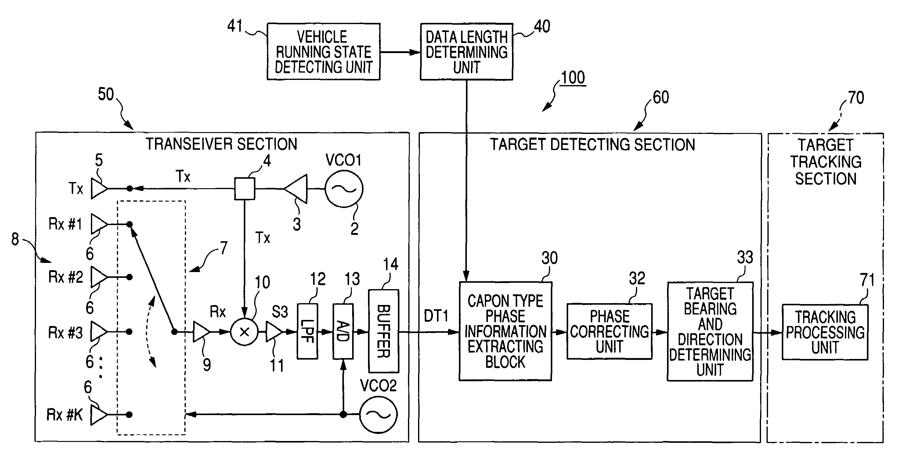
[0042]FIG. 4 is a block diagram of a target detecting apparatus using an electronically agile radar according to the first embodiment, while FIG. 5 is a block diagram of a Capon type phase information extracting unit shown in FIG. 4. FIG. 6 is a view explanatorily showing three search areas determined by dividing a fan-shaped measuring region placed in front of a present vehicle. FIG. 7 is a view schematically showing the processing for extracting short time serial data from sampled digital data.

[0043]An electronically agile radar of a target detecting apparatus 100 shown in FIG. 4 is a type of FM-CW radar for frequency-modulating a continuous wave to obtain a transmission signal Tx having a carrier wave and outputting the signal Tx. The electronically agile radar is also a type of digital beam forming radar for performing the digital beam forming processing for a reception signal Rx received in the radar. A microwave is used as the carrier wave (or radio wave) of the signal Tx. Fur...

first modification

of First Embodiment

[0092]FIG. 11 is a block diagram of a target detecting apparatus using an electronically agile radar according to a first modification of the first embodiment, while FIG. 12 is a block diagram of a variable data length type phase information extracting block shown in FIG. 11.

[0093]As shown in FIG. 11, a target detecting apparatus 110 differs from the apparatus 100 shown in FIG. 4 in that the apparatus 110 has a variable data length type phase information extracting block 42 in place of the block 30. The extracting block 42 extracts, from the reception data DT, phase information expressed by short time serial data of which a data length is changeably adjusted based on a distance of a search area from the present vehicle.

[0094]As shown in FIG. 12, the extracting block 42 has the BPF 18, the extracting unit 19, and a phase information producing unit 43. The producing unit 43 produces phase information from (N−M+1) time series of M short time data of each channel acco...

second modification

of First Embodiment

[0096]FIG. 13 is a block diagram of a target detecting apparatus using an electronically agile radar according to a second modification of the first embodiment, while FIG. 14 is a block diagram of an FFT type phase information extracting block shown in FIG. 13.

[0097]As shown in FIG. 13, a target detecting apparatus 120 differs from the apparatus 100 shown in FIG. 4 in that the apparatus 120 has an FFT type phase information extracting block 44 in place of the block 30. The extracting block 44 extracts, from the reception data DT according to the FFT, phase information expressed by short time serial data of which a data length is changeably adjusted based on a distance of a search area from the present vehicle.

[0098]As shown in FIG. 14, the extracting block 44 has the BPF 18, the extracting unit 19, and an FFT-based phase information producing unit 45. The producing unit 45 produces FFT type phase information from (N−M+1) time series of M short time data of each ch...


PUM


Abstract

A target detecting apparatus mounted on a vehicle has an electronically agile radar detecting a beat signal indicating a difference in frequency between transmission and reception signals and producing a time series of N reception data from the beat signal, a determining unit determining search areas placed at different ranges of distance from the vehicle while considering a running state of the vehicle and determining a data length for each search area, an extracting unit extracting (N−M+1) time series of short time data, respectively, having the data length corresponding to M reception data from the N reception data for each search area, a producing unit producing phase information from the short time data for each search area, and a detecting unit determining a target distance and a target bearing from the phase information and detecting a target from the target distance and the target bearing.

Description

CROSS-REFERENCE TO RELATED APPLICATION[0001]This application is based upon and claims the benefit of priority of the prior Japanese Patent Application 2006-278416 filed on Oct. 12, 2006 so that the contents of which are incorporated herein by reference.BACKGROUND OF THE INVENTION[0002]1. Field of the Invention[0003]The present invention relates generally to a target detecting apparatus using a frequency-modulated continuous wave (FM-CW) type electronically agile radar mounted on a vehicle, and more particularly to the apparatus for detecting a target placed in front of the vehicle by determining a target position and a target bearing.[0004]2. Description of Related Art[0005]To prevent a vehicle collision or to control a distance between two vehicles, a radar mounted on a present vehicle has been developed. This radar measures a target distance from the present vehicle to a forward target such as a precedent vehicle placed in front of the present vehicle, a relative speed of the pres...

Claims


Application Information

Patent Timeline
Patent Type & Authority Patents(United States)
IPC IPC(8): G01S13/06G01S13/08G01S13/32G01S13/00G01S13/93G01S13/931
CPCG01S3/74G01S13/34G01S13/931G01S13/42G01S2013/9375G01S2013/9353G01S2013/932G01S2013/93271
Inventor SUZUKI, KOICHIROYAMANO, CHIHARUNATSUME, KAZUMA
Owner DENSO CORP
Why Eureka
Try Eureka