Fixing apparatus and image forming apparatus

a technology of fixing apparatus and forming apparatus, which is applied in the direction of electrographic process apparatus, instruments, optics, etc., can solve the problems of poor temperature control and achieve the effect of reliable temperature control

Inactive Publication Date: 2010-02-16
OKI DATA CORP
View PDF14 Cites 3 Cited by
  • Summary
  • Abstract
  • Description
  • Claims
  • Application Information

AI Technical Summary

Benefits of technology

[0006]An Object of the invention is to provide a fixing apparatus that provides reliable temperature control.
[0016]The fixing apparatus further includes a release agent applying member is disposed such that the endless belt is sandwiched between the sheet heating element and the release agent applying member, the release agent applying member applying a release agent to the endless belt for facilitating smooth removal of a recording medium from the endless belt after fixing.

Problems solved by technology

However, the conventional fixing apparatus is disadvantageous in that the temperature drop is significant when toner is fused into a recording medium and therefore temperature control is poor.

Method used


Image

  • Fixing apparatus and image forming apparatus
  • Fixing apparatus and image forming apparatus
  • Fixing apparatus and image forming apparatus

Examples


first embodiment

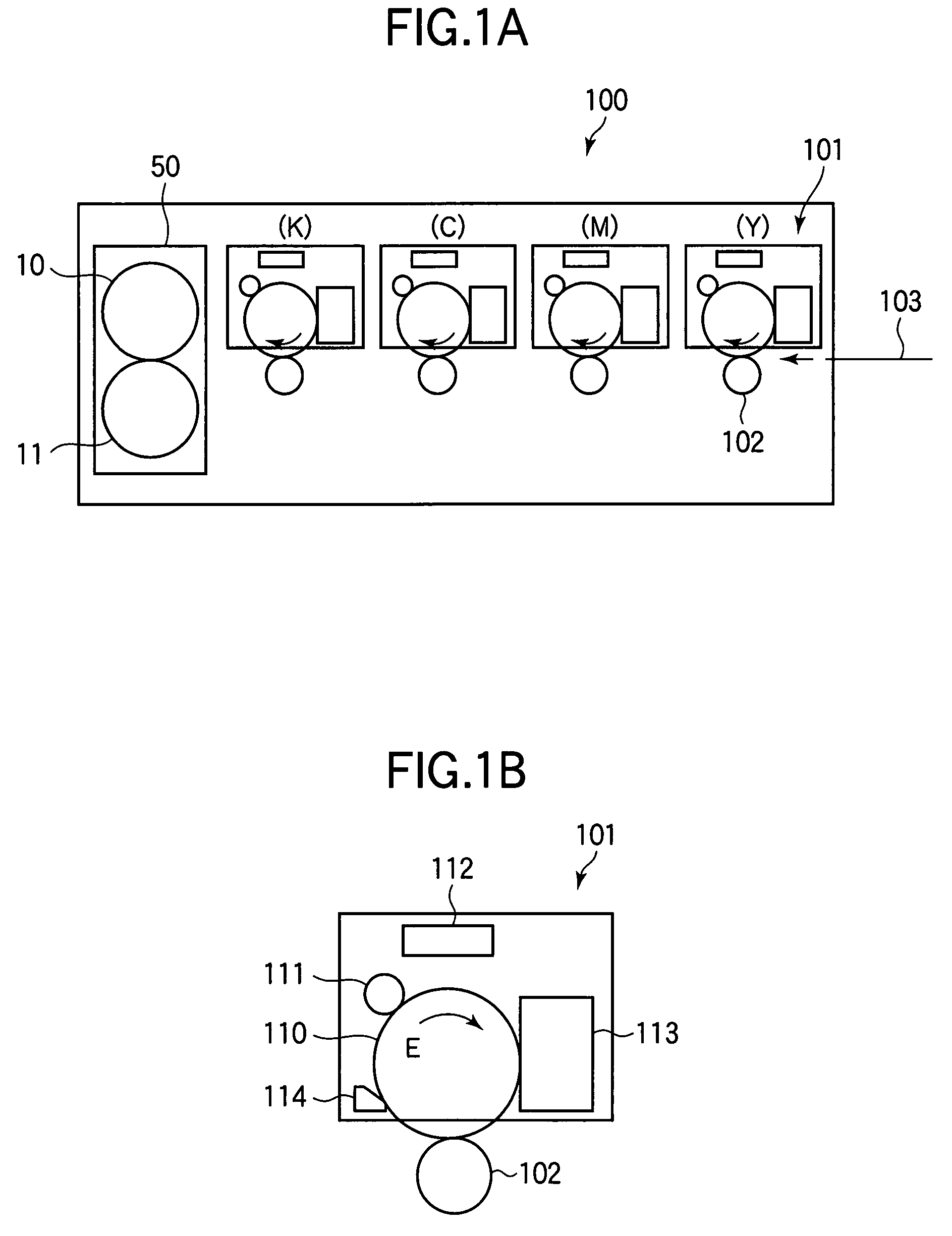
[0032]FIG. 1A illustrates a general configuration of an image forming apparatus 100 equipped with a fixing apparatus according to the invention.

[0033]Referring to FIG. 1A, the image forming apparatus 100 is an electrophotographic printer including image forming sections for forming yellow (Y), magenta (M), cyan (C), and black (K) images. Each image forming section 101 forms an image of a corresponding color. The image forming sections are aligned from upstream to downstream with respect to the direction of transportation of a recording medium 103. The image forming sections are configured in the same way; for simplicity's sake only the operation of a cyan image forming section will be described, it being understood that other image forming sections may work in a similar fashion.

[0034]FIG. 1B illustrates a general configuration of a pertinent portion of an image forming section 101 for cyan. Referring to FIG. 1B, the image forming section 101 includes a photoconductive drum 110 that ...

second embodiment

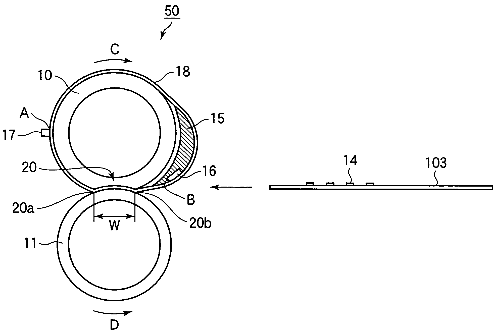
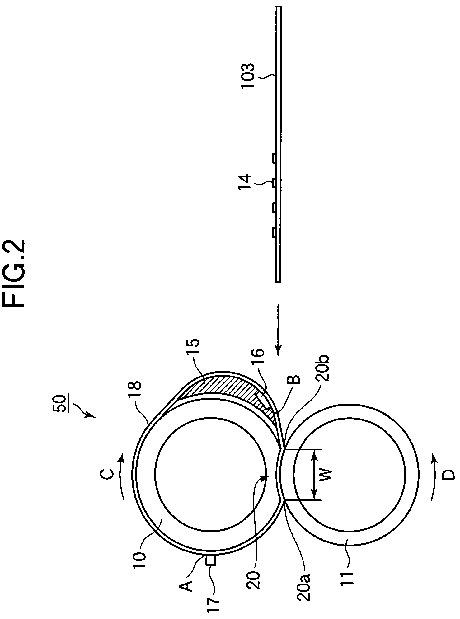
[0081]FIG. 6 illustrates a pertinent portion of a fixing unit 150.

[0082]The fixing unit 150 differs from the fixing unit 50 in that a release agent applying member 151 is employed. Elements similar to those in the first embodiment have been given the same reference numerals and the description thereof is omitted.

[0083]Referring to FIG. 6, the fixing belt 18 is entrained about a fixing roller 10 and a support 15 that supports a heater 16 in the form of a sheet heating element. The heater 16 and the support 15 press the fixing belt 18 from inside. The support 15 has a concave surface configured to the surface of the photoconductive drum 110 and a convex surface in contact with the inside surface of the fixing belt 18. The heater 16 is embedded in the support 15 and has a convex surface exposed on the convex surface of the support 15 such that the convex surface of the heater 16 is a part of the convex surface of the support 15. In other words, the convex surface of the heater 16 is fl...


PUM


Abstract

A fixing apparatus includes an endless belt, a fixing roller, a pressure roller, a sheet heating element, and a support. The fixing roller and support are positioned on the inside of the endless belt. The endless belt is entrained about the fixing roller and the support. The support supports the sheet heating element. The pressure roller is positioned on the outside of the endless belt. The pressure roller cooperates with the fixing roller to hold the endless belt between the fixing roller and the pressure roller in sandwiched relation such that a nip is formed between the endless belt and the pressure roller. The sheet heating element is in contact with the inside of the endless belt and heats the endless belt. The sheet heating element is disposed in an area outside of the nip.

Description

BACKGROUND OF THE INVENTION[0001]1. Field of the Invention[0002]The present invention relates to a fixing apparatus and an image forming apparatus that incorporates the fixing apparatus.[0003]2. Description of the Related Art[0004]Conventional monochrome or color image forming apparatuses include copying machines, printers, and facsimile machines. These apparatuses use a fixing apparatus. One of conventional fixing apparatuses is configured such that a fixing belt is held between a heater and a pressure roller in sandwiched relation.[0005]This type of fixing apparatus is advantageous in that the overall heat capacity of the fixing apparatus is relatively small, and therefore a fixing temperature may be reached in a very short time after power up of the apparatus, and in that power consumption is low. However, the conventional fixing apparatus is disadvantageous in that the temperature drop is significant when toner is fused into a recording medium and therefore temperature control i...

Claims


Application Information

Patent Timeline
Patent Type & Authority Patents(United States)
IPC IPC(8): G03G15/20
CPCG03G15/2039G03G2215/2016G03G2215/2029
Inventor KIMURA, TAKU
Owner OKI DATA CORP
Why Eureka
Try Eureka