
Apparatus for generating digital lane mark

a technology applied in the field of analog and digital lane markers, can solve the problems of insufficient accuracy of map database for feedback control and preview control of vehicles, inability to properly use information, and inability to correct errors of driving orbit caused by these kinds of conditions and circumstances. high accuracy

Active Publication Date: 2010-02-16
SANEI KK
View PDF7 Cites 5 Cited by
  • Summary
  • Abstract
  • Description
  • Claims
  • Application Information

AI Technical Summary

Benefits of technology

"The patent text describes a digital lane mark generation apparatus for vehicles and aircraft that can accurately generate a driving orbit map using GPS, gyro sensor, and camera images. The apparatus can also account for various conditions such as poor visibility, road surface roughness, and weather factors. The generated map can be used for accurate navigation and control of the vehicle. The technical effects of this invention include improved accuracy and efficiency of vehicle navigation and control, as well as reduced processing load on the system and improved processing ability of the vehicle."

Problems solved by technology

Moreover, such information cannot be properly used when visibility is poor because of a frost, a snowfall, weather conditions, the night time, a curved road, and a top of a hill
Also, according to the vehicle system using a map database of the car navigation system, there is a problem that the map database is not sufficiently accurate for the feedback control and the preview control of the vehicle.
Moreover, during actual driving of the vehicle, the vehicle may drive out of the calculated driving orbit generated by the system because of the various conditions and circumstances of the vehicle such as a one-sided load, a one-sided break, a speed change of the vehicle by acceleration or deceleration, and a structural unbalance, or because of the various conditions and circumstances of a road structure such as a longitudinal gradient and a crossing gradient cant of the road.
Hence, the errors of the driving orbit caused by these kinds of conditions and circumstances have to be corrected.
However, the shorter interval sampling requires the shorter processing time of information from the GPS, which increases the load on the system to cause the problem of processing ability of the system.

Method used


Image

  • Apparatus for generating digital lane mark
  • Apparatus for generating digital lane mark
  • Apparatus for generating digital lane mark

Examples


Embodiment Construction

[0048]Below, an embodiment of a digital lane mark generation apparatus of the invention is explained, referring to the drawings.

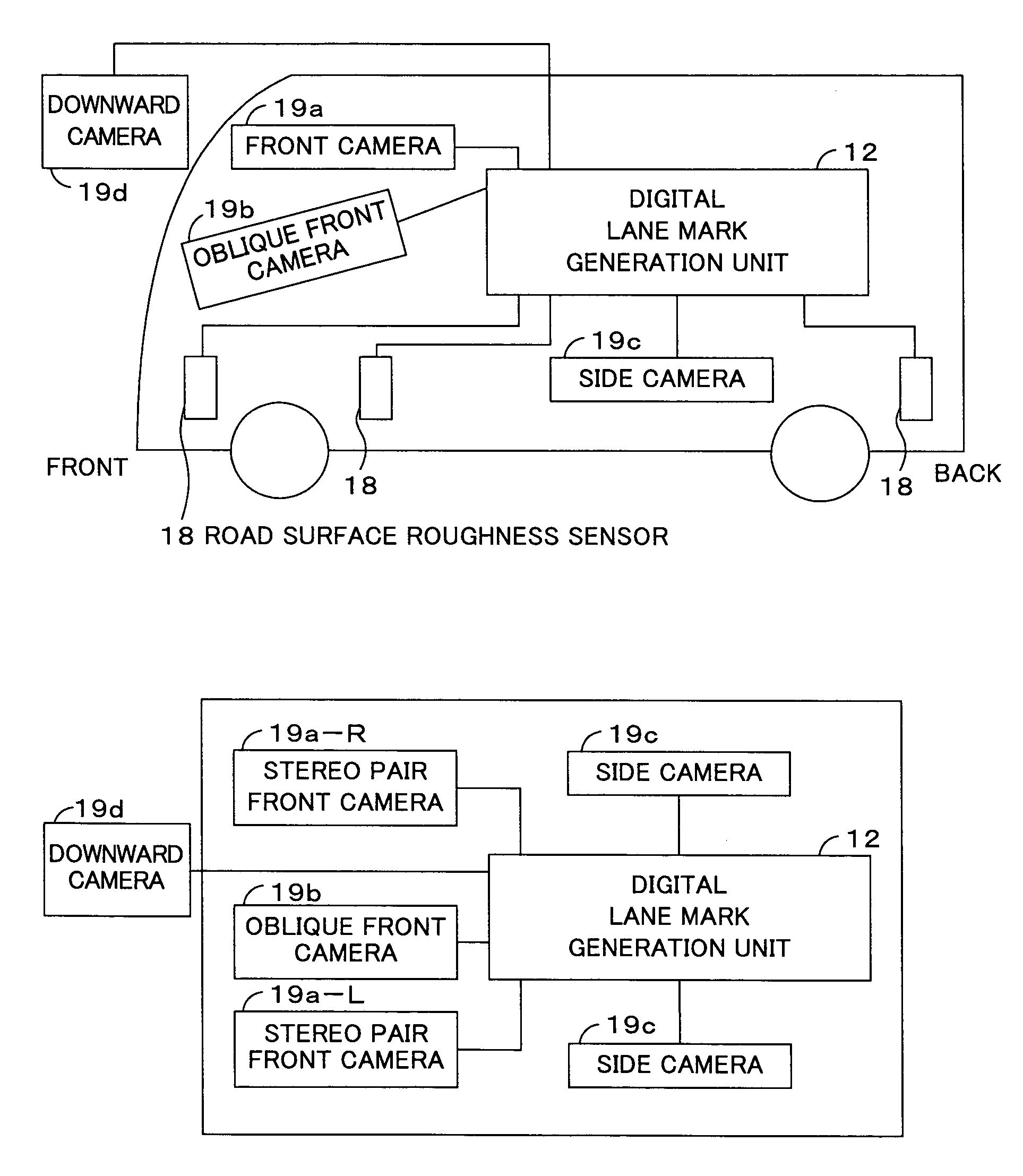
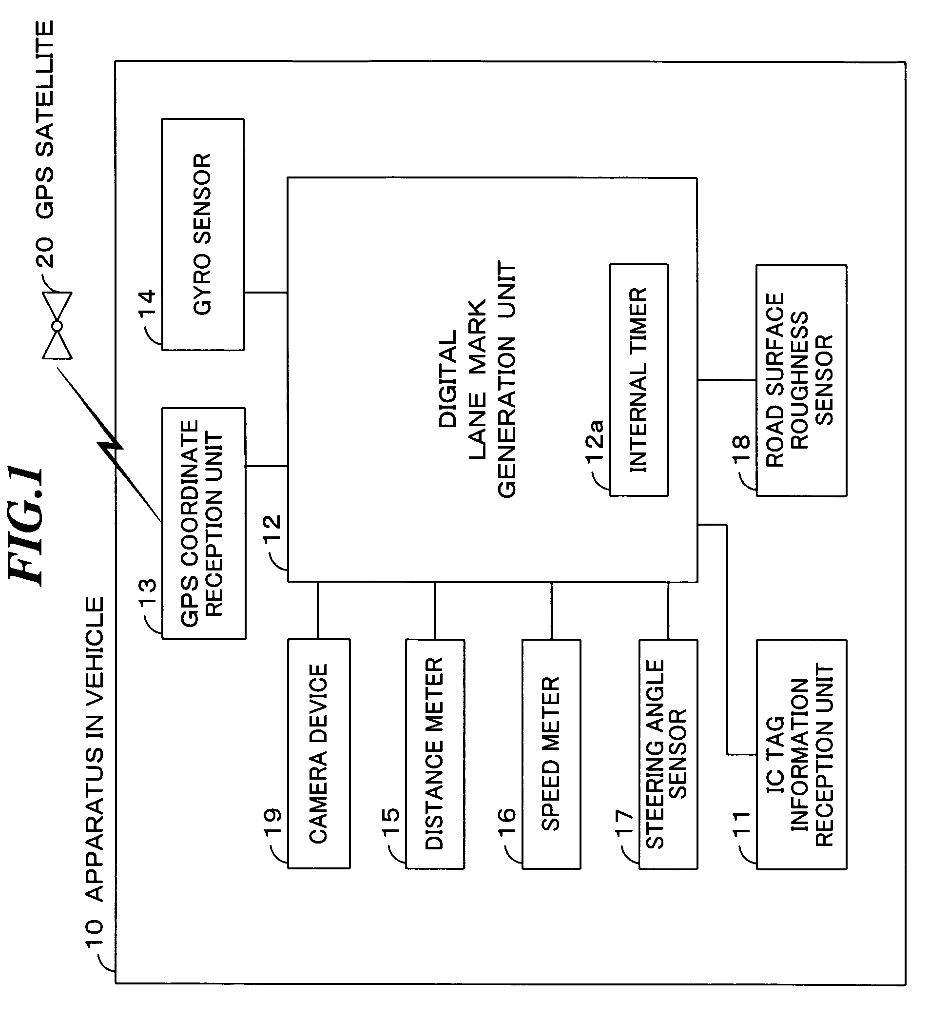
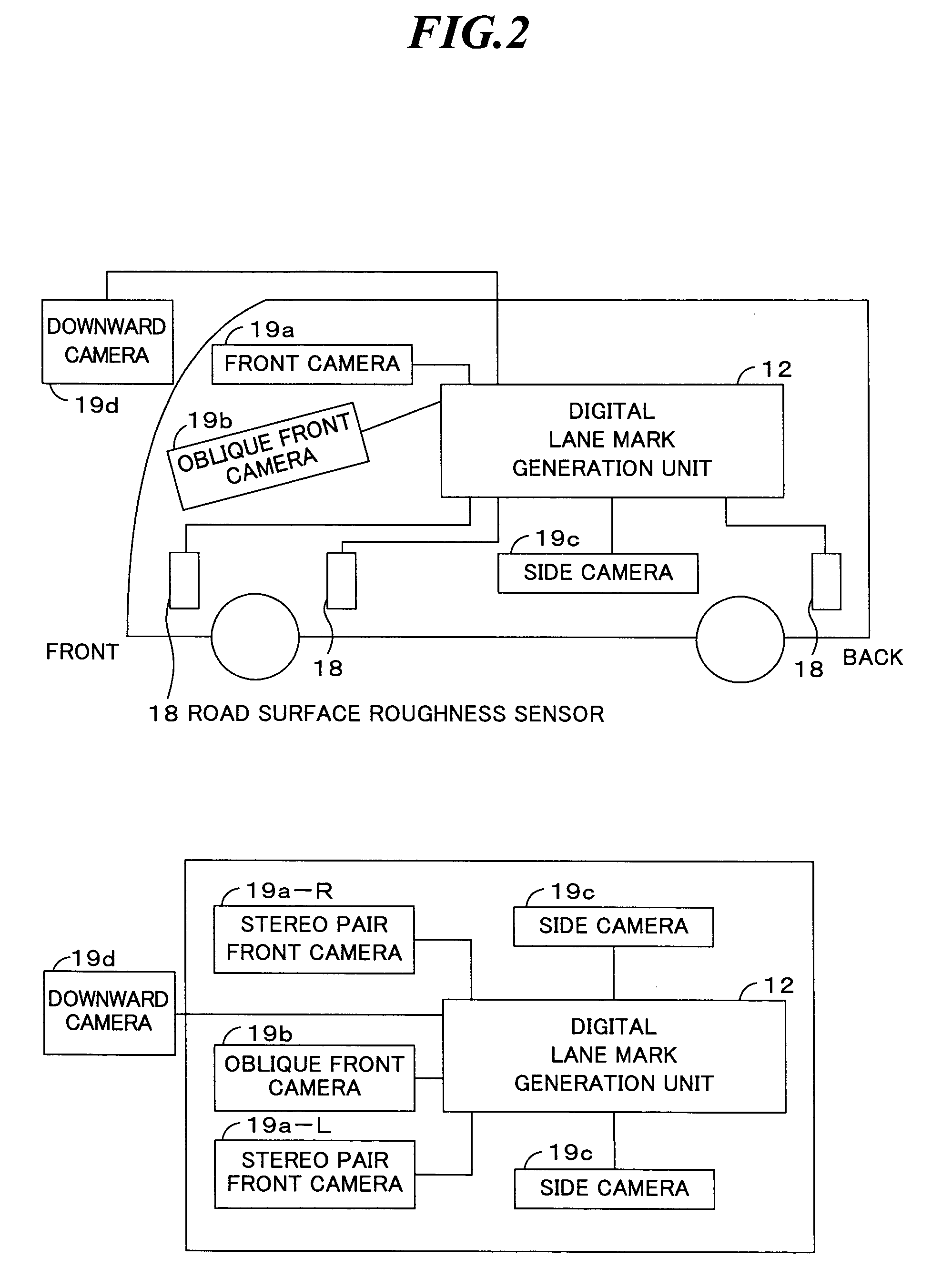
[0049]FIG. 1 shows a digital lane mark generation apparatus of this invention. This digital lane mark generation apparatus is a digital lane mark generation apparatus in a vehicle (an apparatus in a vehicle) 10, which is for generating a digital lane mark indicating the driving orbit of a vehicle. The apparatus includes a GPS coordinate reception unit 13, which obtains GPS coordinates which are global geodetic coordinates (X, Y, Z) of the vehicle from a GPS satellite 20; a gyro sensor 14, which calculates measurement values of a gradient (ψ, θ, φ) by measuring a gradient of the vehicle; one or more camera devices 19, which photograph the outside of the vehicle as a camera image; a distance meter 15, which measures a driving distance measuring point (l) of the driving distance of the vehicle; a speed meter 16, which measures speed of the vehicle (v); a steer...


PUM


Abstract

A digital lane mark generation apparatus generates a highly accurate and inexpensive three-dimensional mathematical expression orbit map (a digital lane mark). The apparatus includes a GPS coordinate reception unit obtaining GPS coordinates (X, Y, Z), a gyro sensor calculating measurement values of a gradient (ψ, θ, φ), a camera device, a distance meter measuring a driving distance measuring point (l), a speed meter measuring a speed, a steering angle sensor measuring a steering angle (ρ), a road surface roughness sensor detecting a road surface roughness (δ), an IC tag information reception unit detecting IC tag position information, an internal timer, and a digital lane mark generation unit generating the digital lane mark by relating obtained information to a standard time, and by using a line segment, a circular arc, and / or a clothoid curve.

Description

TECHNICAL FIELD[0001]This invention relates to an apparatus for generating a digital lane mark indicating the driving orbit of a vehicle like a car. In particular, this invention relates to an apparatus for generating a highly accurate and inexpensive three dimensional mathematical expression orbit map (the digital lane mark).BACKGROUND ART[0002]Conventionally, there are a driving support apparatus to support driving a vehicle like a car safely and an automatic driving apparatus to drive a vehicle automatically. For example, Japanese Patent Laid-open No. 11-212640 and Japanese Patent Laid-open No. 10-261193 disclose such examples. Below, conventional vehicle systems to drive a car automatically are explained.[0003]The conventional vehicle system installed in each vehicle obtains traffic conditions of the driving route from the GPS (Global Positioning System) to calculate the best driving route and the system drives a car automatically based on (i) position information of lane marks ...

Claims


Application Information

Patent Timeline
Patent Type & Authority Patents(United States)
IPC IPC(8): G06K9/00
CPCG01C21/26
Inventor YAMAMOTO, TADASHI
Owner SANEI KK
Learn More