Metal-faced building panels having angled projections in longitudinal edge recesses for mating with locking ramps on flanges of concealed I-shaped connector

a technology of metal-faced building panels and longitudinal edges, which is applied in the direction of girders, walls, joists, etc., can solve problems such as interference fit, and achieve the effect of increasing structural properties

Inactive Publication Date: 2010-02-23
WOLFE DORALBA H
View PDF28 Cites 46 Cited by
  • Summary
  • Abstract
  • Description
  • Claims
  • Application Information

AI Technical Summary

Benefits of technology

[0027]Further, an object of the present invention is to provide an edge coupling that does not require stitching with a mechanical fastener along the entire longitudinal edge, as is required wit the prior art, thereby creating a strong and continuous diaphragm along the enti...

Problems solved by technology

This creates an interference fit at the...

Method used


Image

  • Metal-faced building panels having angled projections in longitudinal edge recesses for mating with locking ramps on flanges of concealed I-shaped connector
  • Metal-faced building panels having angled projections in longitudinal edge recesses for mating with locking ramps on flanges of concealed I-shaped connector
  • Metal-faced building panels having angled projections in longitudinal edge recesses for mating with locking ramps on flanges of concealed I-shaped connector

Examples


Embodiment Construction

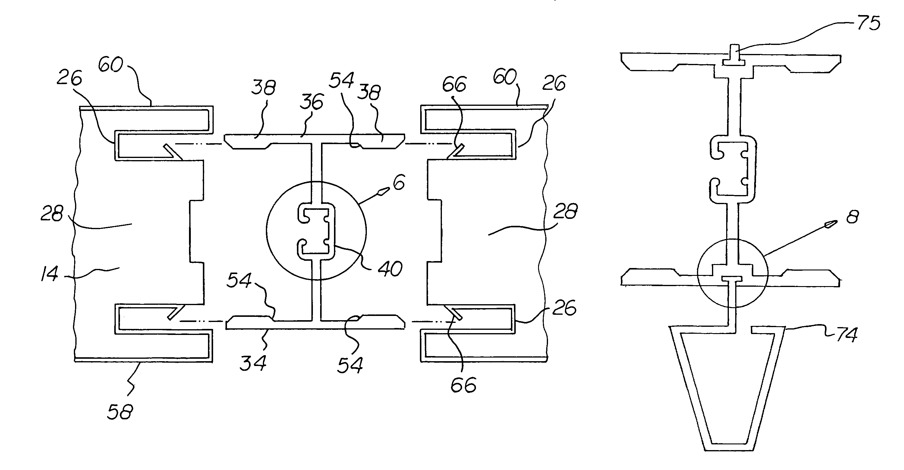
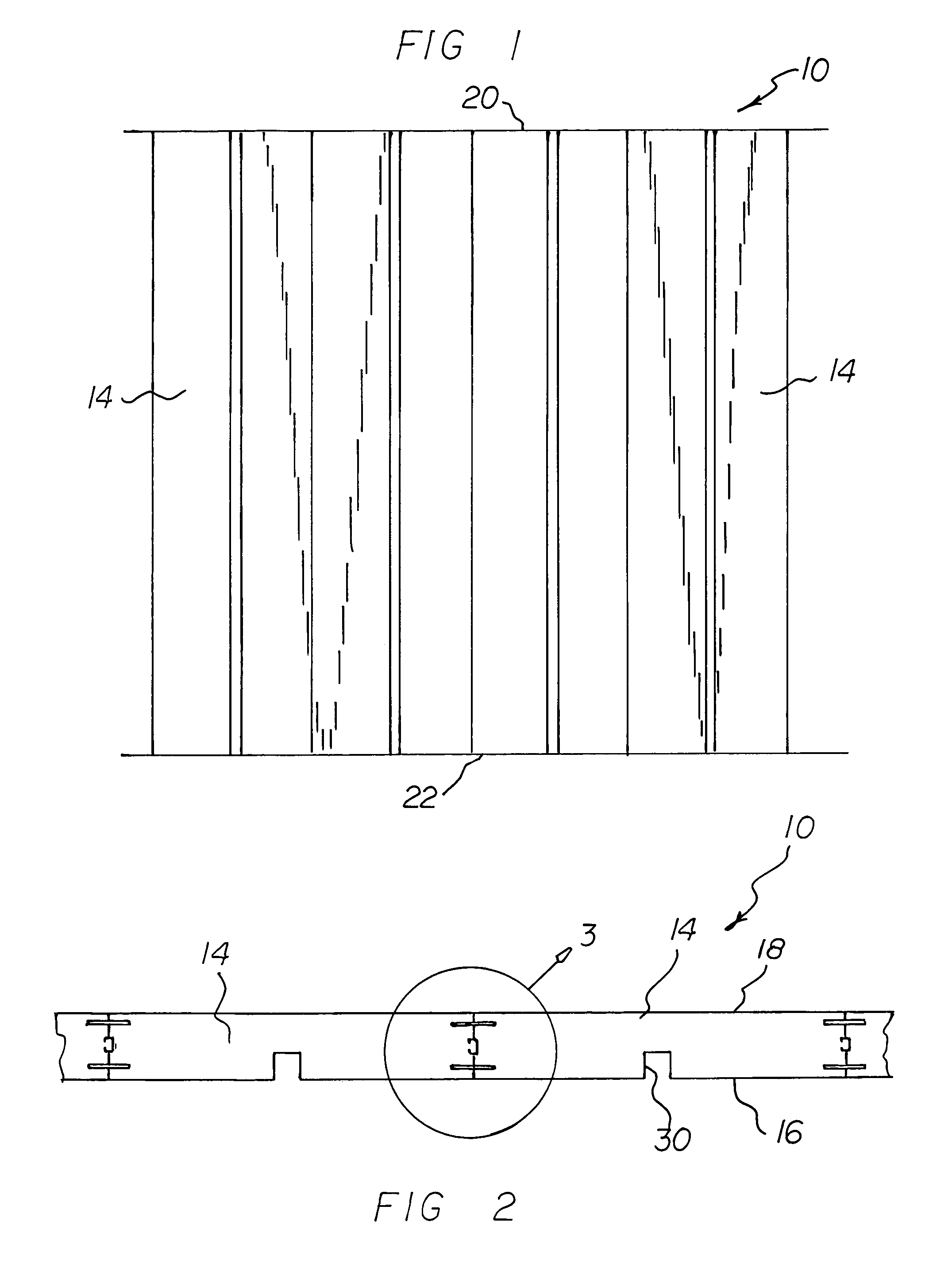
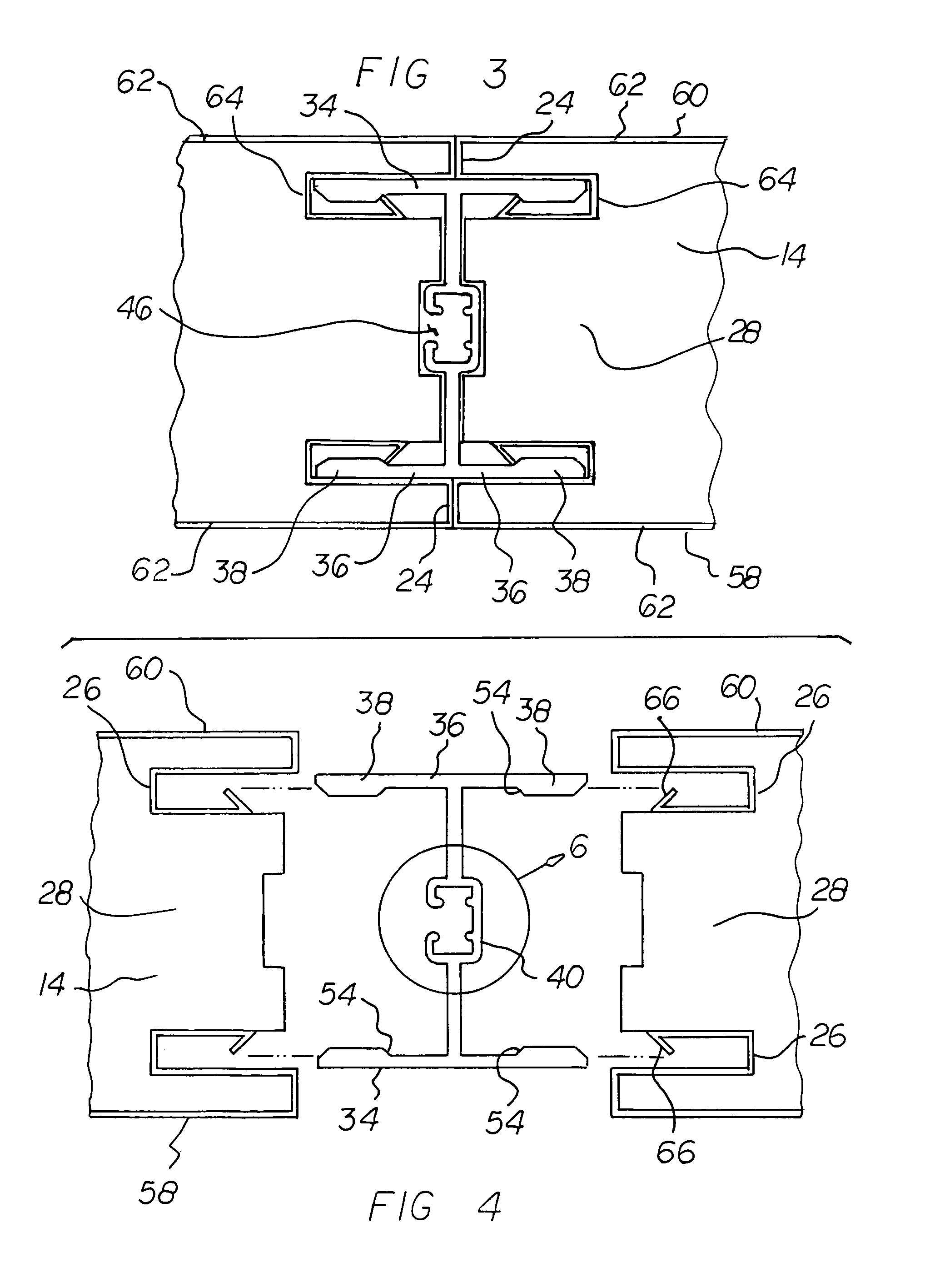
[0045]With reference now to the drawings, and in particular to FIG. 1 thereof, the preferred embodiment of the new and improved structural wall and roof assembly embodying the principles and concepts of the present invention and generally designated by the reference numeral 10 will be described.

[0046]The present invention, the structural wall and roof assembly 10 is comprised of a plurality of components. Such components in their broadest context include metal faced insulated inserts and concealed locking beams. Such components are individually configured and correlated with respect to each other so as to attain the desired objective.

[0047]It is important to differentiate the present invention, which is a wall and roof assembly, from the prior art, which are individual panels. In the prior art the individual panels comprising a wall or roof system are considered to be components and / or cladding materials under the definition of most model building codes and standards. This limits th...


PUM


Abstract

Metal faced insulated inserts have interior and exterior surfaces with parallel longitudinal edges between an upper and lower short edge. Each longitudinal edge of each insert has two deep recesses and a central shallow recess. A plurality of generally I-shaped concealed locking beams have a central section and parallel end sections. Each end section has a central region of a thickness less than end regions to form a locking ramp. A pair of similarly configured metal facings for each concealed locking beam with opposed end parts are located within the deep recesses at the longitudinal edges of each insert. Each end part terminates in a V-shaped projection configured to allow the end regions of the concealed edge lockings to compress the V-shaped projections and allow the end regions of the concealed locking beams to mate with the metal facings.

Description

RELATED APPLICATIONS[0001]The present application is a continuation-in-part application of U.S. patent application Ser. No. 10 / 677,773 filed Oct. 2, 2003, now U.S. Pat. No. 7,021,014, which is in turn a continuation-in-part application of U.S. patent application Ser. No. 09 / 788,793 filed Feb. 20, 2001, now abandoned, the subject matter of which applications is incorporated herein by reference.BACKGROUND OF THE INVENTION [0002]1. Field of the Invention[0003]The present invention relates to a structural wall and roof assembly and more particularly pertains to coupling metal faced insulated inserts with concealed locking beams.[0004]2. Description of the Prior Art[0005]The use of building systems of known designs and configurations is known in the prior art. More specifically, building systems of known designs and configurations previously devised and utilized for the purpose of building through known methods and apparatuses are known to consist basically of familiar, expected, and obv...

Claims


Application Information

Patent Timeline
IPC IPC(8): E04B2/00
CPCE04B1/14E04B5/023E04B5/04E04B7/22E04B7/24E04C3/06E04D3/352E04B1/615E04C2003/0421E04C2003/0434E04C2003/0452
Inventor WOLFE, MICHAEL J.
Owner WOLFE DORALBA H
Why Eureka
Try Eureka