
Vehicle bumper and method of making same

a technology for bumpers and vehicles, applied in the direction of bumpers, vehicle components, vehicular safety arrangements, etc., can solve the problems of cost prohibitive use of roll forming to make a complex bumper configuration or cross-section, and limit the shape and configuration of roll forming, so as to reduce the overall forming cost

Inactive Publication Date: 2010-02-23
SKD AUTOMOTIVE GRP
View PDF40 Cites 18 Cited by
  • Summary
  • Abstract
  • Description
  • Claims
  • Application Information

AI Technical Summary

Benefits of technology

"The present invention is a vehicle bumper and a method of making it. The bumper consists of two U-shaped members that fit together to form the bumper. The first member has first and second sidewalls connected by a base, and the second member has first and second sidewalls connected by a base. The first and second members are positioned together so that their respective sidewalls are adjacent and joined together. The bumper has a cross-section that varies along the longitudinal axis of the first and second members. The first and second U-shaped members have detents on their outer surface to properly position them with respect to each other. The method involves stamping the first and second U-shaped members from a flat sheet of high-strength material, which allows for the formation of multiple shapes and configurations. This method reduces overall forming cost as only one forming tool is required and the single-member can be formed using a stamping process."

Problems solved by technology

While roll forming is a particularly attractive manufacturing method for mass producing bumper beams using high-strength materials, roll forming limits the shape and configuration of the bumper.
In addition using roll forming to make a complex bumper configuration or cross-section is often cost prohibitive.

Method used


Image

  • Vehicle bumper and method of making same
  • Vehicle bumper and method of making same
  • Vehicle bumper and method of making same

Examples


Embodiment Construction

[0028]The following description of the preferred embodiment(s) is merely exemplary in nature and is in no way intended to limit the invention, its application, or uses.

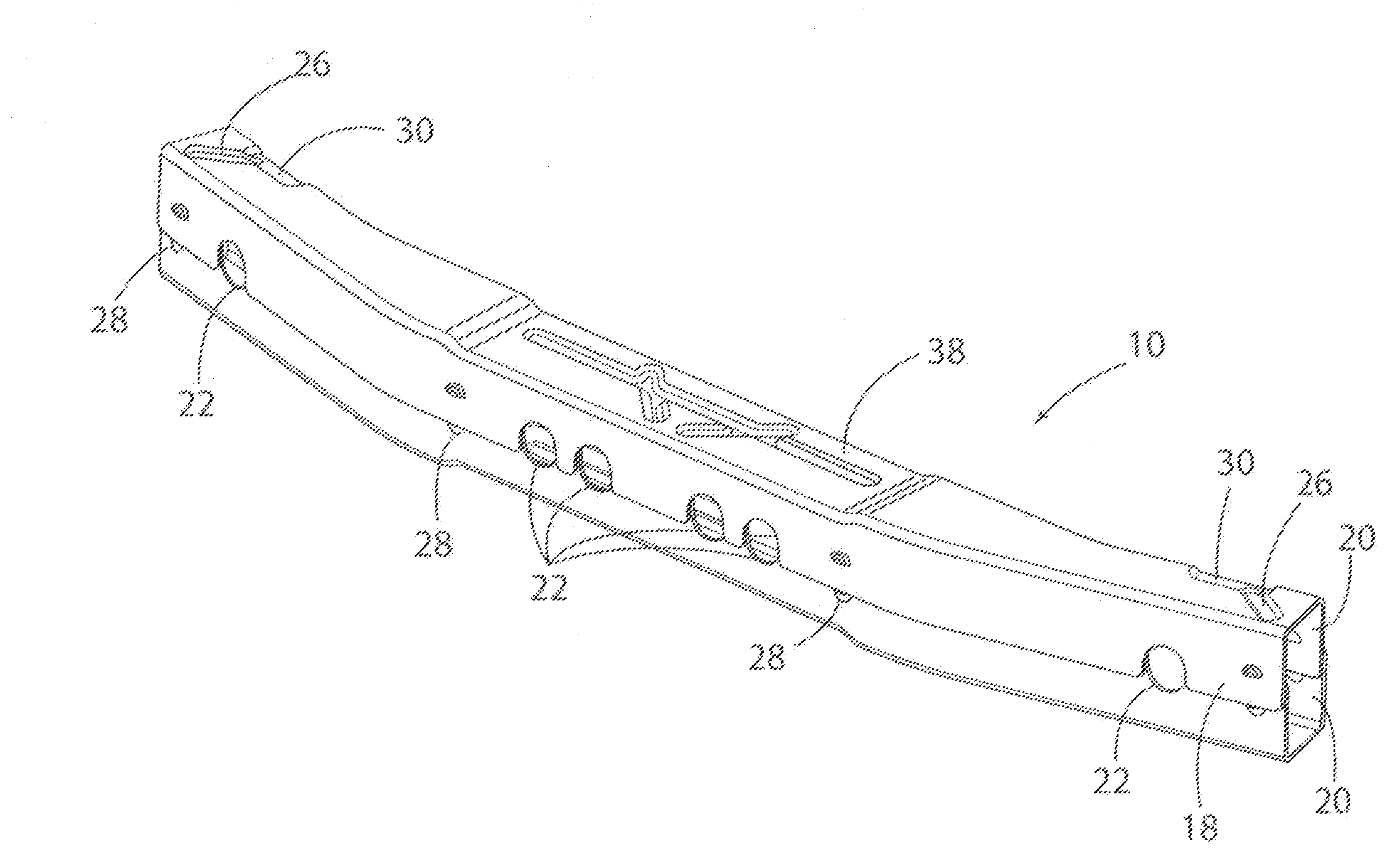
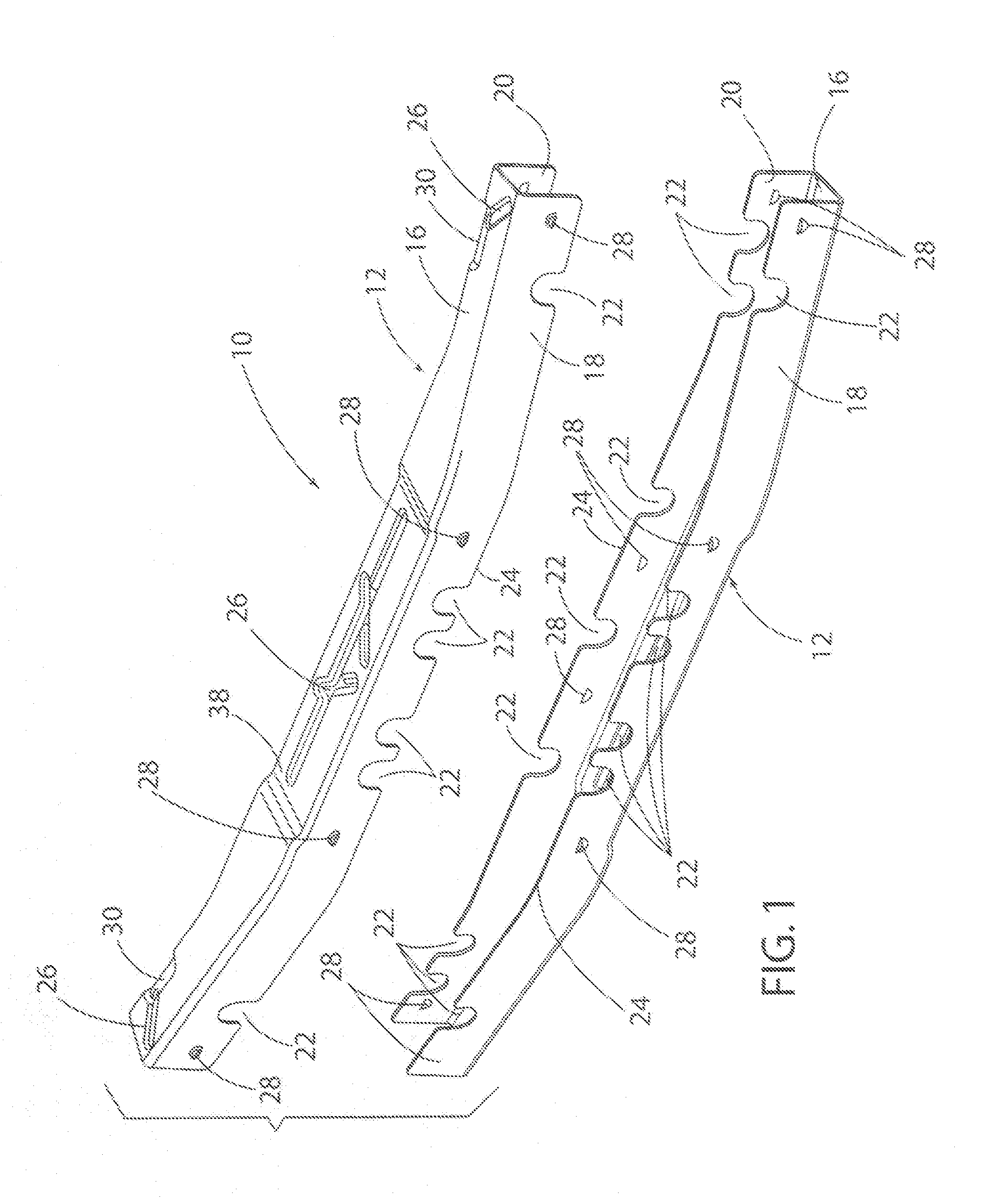
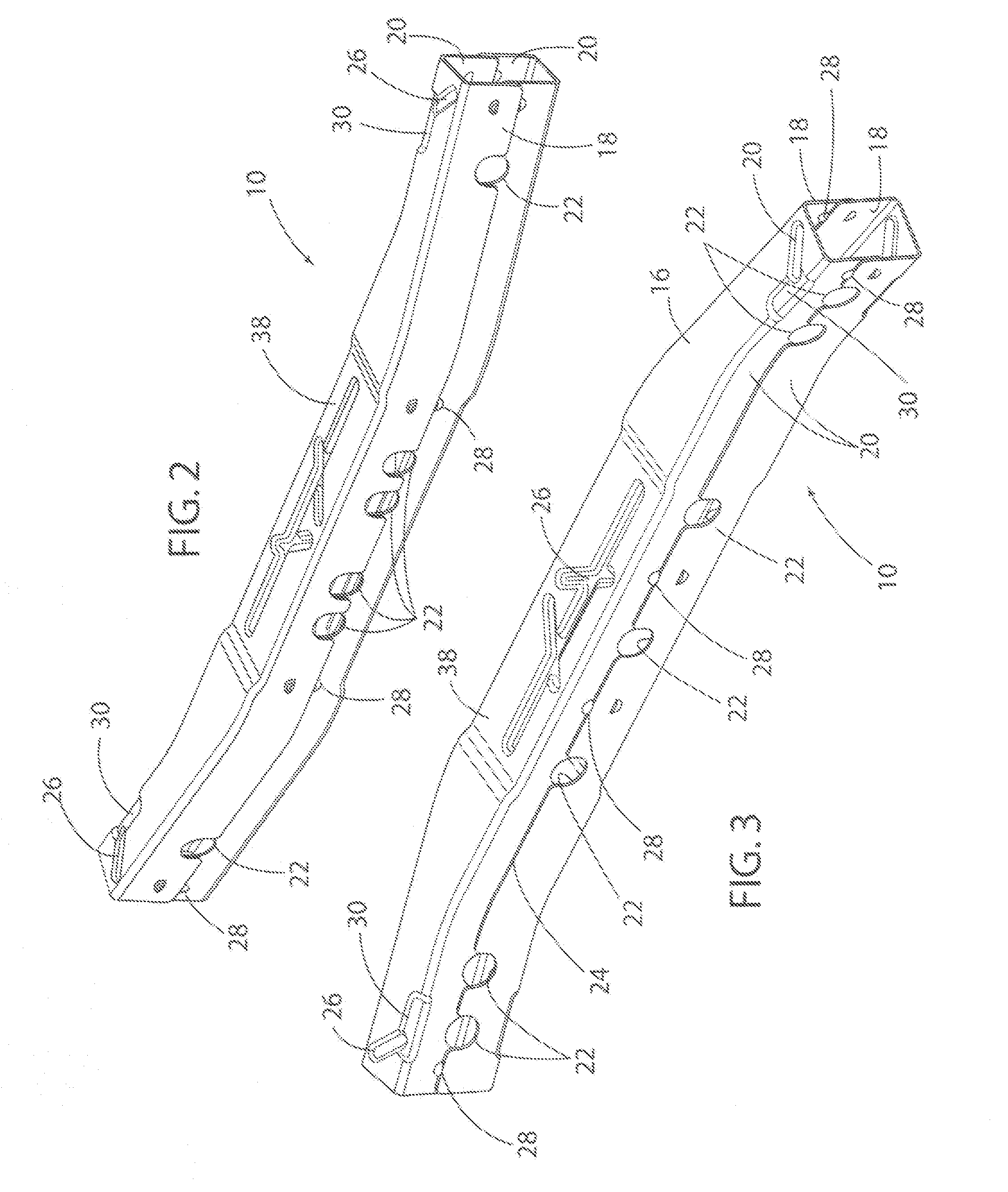
[0029]Turning now to the drawings, specifically FIGS. 1-5, there is shown a bumper, seen generally at 10, according to the present invention. The bumper 10 includes upper and lower members or sections 12 that fit together to form the bumper 10. In the preferred embodiment, the upper and lower members or sections 12 are identical. Accordingly, the manufacturing process forms only one member thereby eliminating the need to form separate upper and lower members. In accordance with the present invention, two identical members are used with one of the members rotated to an upside down position. As illustrated, the member 12 has a substantially C-shaped or U-shaped cross-section including a base portion 16 and a pair of sidewalls 18, 20 that extend outward from the base portion 16.

[0030]In addition, the member 12 further in...


PUM


Abstract

A vehicle bumper and a method for making a vehicle bumper formed of first and second members. Each of the first and second members are formed of substantially similar first and second U-shaped members positioned such that the respective sidewalls of the first and second U-shaped members are positioned adjacent one another. The bumper including a plurality of apertures therein formed by cutouts extending inward from the peripheral edge of each of the first and second U-shaped members.

Description

CROSS-REFERENCE TO RELATED APPLICATIONS[0001]This application claims the benefit of U.S. Provisional Application No. 60 / 764,569, filed Feb. 2, 2006,BACKGROUND OF THE INVENTION[0002]1. Field of the Invention[0003]The present invention relates generally to a bumper for a vehicle.[0004]2. Description of Related Art[0005]Motor vehicles typically use a bumper system at the front and rear end thereof. The bumper system typically includes a bumper beam that extends across the front and rear end of the vehicle. The respective bumper beams are typically attached to either a pair of rails or the vehicle frame. Many bumper systems include an energy absorption member that extends across and is secured to the bumper beam. In some cases, the bumper system includes a facia or cover located over the bumper beam.[0006]The motor vehicle industry has established certain standards and must adhere to certain government regulations concerning low-speed vehicle impact. Further, vehicle bumpers are typical...

Claims


Application Information

Patent Timeline
Patent Type & Authority Patents(United States)
IPC IPC(8): B60R19/02
CPCB60R19/18B60R2019/1826
Inventor HENSELEIT, KARL
Owner SKD AUTOMOTIVE GRP
Learn More