Vehicle lamp

a technology for vehicle lamps and reflectors, which is applied in the direction of point-like light sources, light and heating equipment, etc., can solve the problems of vehicle lamps not being able to conform to light distribution standards, vehicle lamps may not have heat dissipation structures, and other components such as reflectors, etc., to achieve improved heat dissipation efficiency, and high conductivity

Inactive Publication Date: 2010-02-23
STANLEY ELECTRIC CO LTD
View PDF6 Cites 5 Cited by
  • Summary
  • Abstract
  • Description
  • Claims
  • Application Information

AI Technical Summary

Benefits of technology

[0027]The presently disclosed subject matter has been devised in view of the above and other characteristics, desires, and problems in the conventional art, and to make certain changes to existing vehicle lamps. Thus, an aspect of the disclosed subject matter includes providing a vehicle lamp including a light source and a casing in which the light source is sealed, wherein a feature of the vehicle lamp can include providing a heat dissipation structure that can prevent the casing and other components from experiencing thermal damage. In addition, because an inner surface of the casing can be used as a reflex surface adjacent a reflector, the heat dissipation structure can result in a small vehicle lamp having a favorable light distribution.
[0031]In the above-described exemplary vehicle lamp, the thermal conductive material can improve heat-radiating efficiency by using a metallic material with high conductivity and can further improve heat-radiating efficiency by increasing a heat-radiating area thereof with the ridged structure. In addition, because the thermal conductive material can adhere between the V-shaped groove with an elasticity of the ridged structure thereof by being inserted into the V-shaped groove, the attachment of the heat dissipation structure can be extremely simple.
[0032]In the above-described exemplary vehicle lamp, the reflector can be configured to be formed integrally with the casing and the inner surface of the casing can be configured to include a reflex surface for reflecting the light emitted from the light source. The reflex surface on the inner surface of the casing can be formed adjacent to the reflector. Thus, the vehicle lamp including the heat dissipation structure of the disclosed subject matter can result in a small vehicle lamp having a favorable light distribution.

Problems solved by technology

In addition, because the miniaturized casing includes a light source that gives out heat in the small sealed casing, positioning for a heat dissipation structure in the vehicle lamp is a major issue as well as a configuration of the vehicle lamp to conform to a light distribution standard.
Because, if the heat dissipation structure cannot normally operate, the casing and other components such as the reflector may deteriorate, transform and / or tarnish.
Accordingly, the vehicle lamp may not be able to conform to a light distribution standard and also may become unable to operate.
Therefore, their outside appearance may not look very good and / or maybe limited with respect to design creativity.
In addition, when reflectors 4 extend in their upwards directions in order to conform to a light distribution standard, it may be difficult or even impossible to extend these reflectors 4 upwards.
Thus, the above-described unexpected light may cause a problem and may not conform to a predetermined light distribution pattern.
Thus, these turnings and / or shavings may cause a defect in the vehicle lamps 1 and 7.
Thus, when the hermetic inner space of the casing 2 is small and the bulb continuously emits for a long time, the vehicle lamp may not be configured properly to prevent the casing 2 and other components from experiencing thermal damage caused by the heat generated from the bulb 3.

Method used


Image

  • Vehicle lamp
  • Vehicle lamp
  • Vehicle lamp

Examples


Embodiment Construction

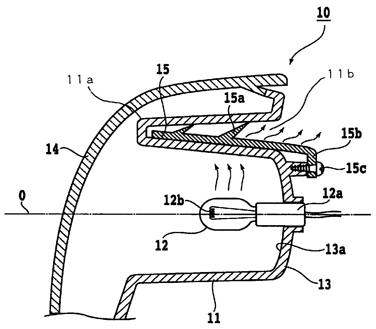
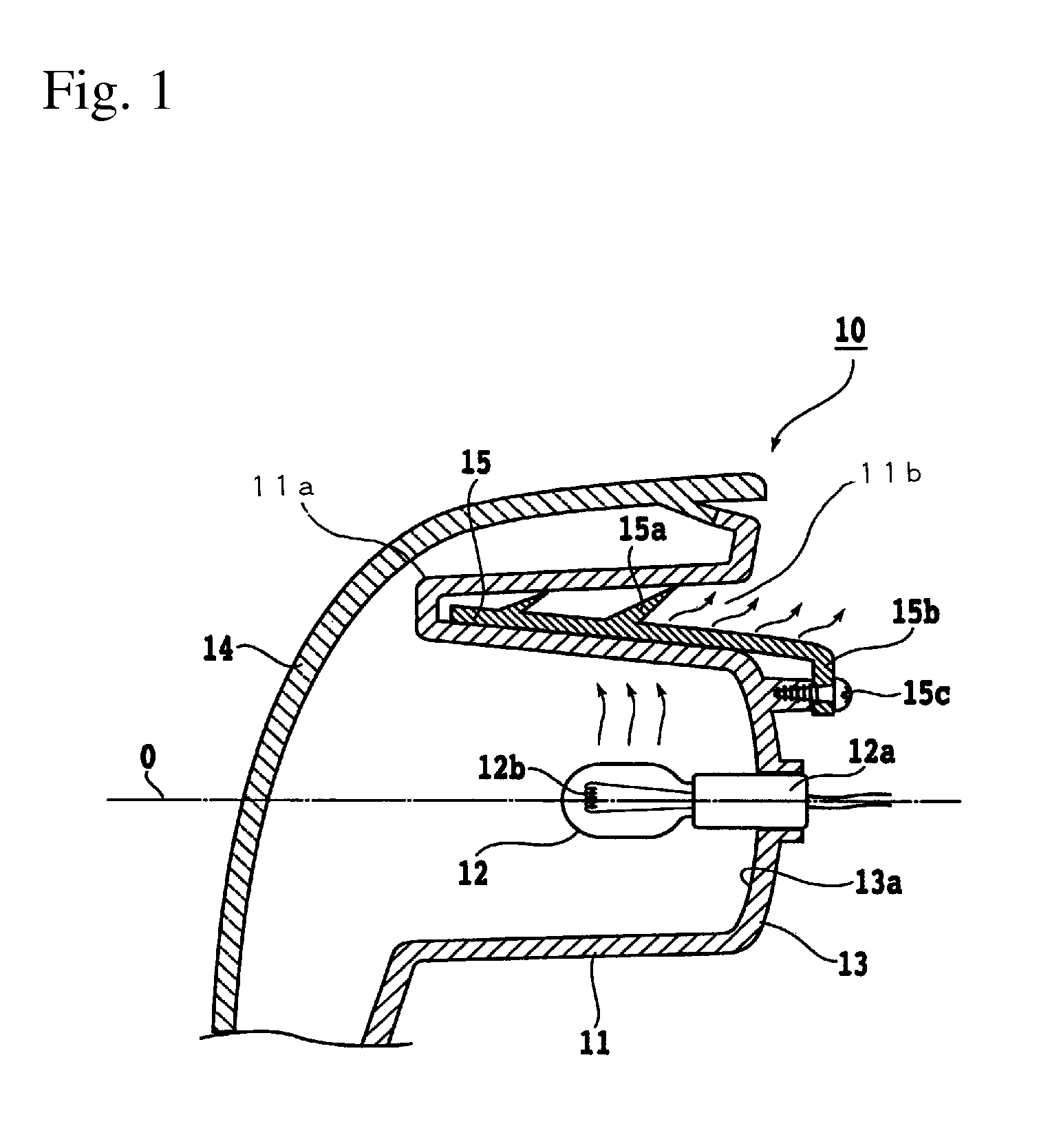
[0038]The disclosed subject matter will now be described in detail with reference to FIGS. 1 to 2. FIG. 1 is a schematic side cross-section view of an exemplary embodiment of a vehicle lamp made in accordance with principles of the disclosed subject matter. The vehicle lamp 1 shown in FIG. 1 is a rear combination lamp that can include a stop lamp, a taillight, a position lamp, a turn-signal lamp, etc.

[0039]The vehicle lamp 1 is not limited to a rear combination lamp and can alternatively be configured as a lamp including at least one of a headlight, a taillight, a positioning light, running light, fog light, traffic light, or other vehicle related lamp, etc.

[0040]The vehicle lamp 10 can include a casing 11, a light source 12, a reflector 13, a front lens 14 and a thermal conductive material 15. The casing 11 can be configured in a tubular shape having both an inner surface and an outer surface. The light source 12 can be included in the reflector 13 that can be composed of a resin, ...


PUM


Abstract

The disclosed subject matter can include a vehicle lamp having a favorable light distribution and an effective heat dissipation structure. The vehicle lamp can include a light source and a casing in which the light source is sealed. The casing can be configured in a tubular shape and a reflector can be configured in a hollow of the casing. The casing can be sealed between the reflector and a front lens configured to allow light emitted from the light source to pass therethrough. The inner surfaces of the casing and the reflector can be configured to form a predetermined light distribution via the front lens. The outer surfaces of the casing and the reflector can be exposed to the outside and can be configured to radiate heat generated from the light source to the outside using heat conductive material. Thus, the lamp can be miniaturized and provide favorable light distribution.

Description

[0001]This application claims the priority benefit under 35 U.S.C. §119 of Japanese Patent Application No. 2007-162022 filed on Jun. 20, 2007, which is hereby incorporated in its entirety by reference.BACKGROUND[0002]1. Field[0003]The presently disclosed subject matter relates to a vehicle lamp that includes a light source and a casing in which the light source is sealed, and more particularly to a vehicle lamp further including a heat dissipation structure that can prevent the casing and other components from experiencing thermal damage.[0004]2. Description of the Related Art[0005]A vehicle can include various vehicle lamps such as a headlight, a taillight, a stop lamp, a position lamp, a turn-signal lamp and the like, which include a light source such as an incandescent bulb, a halogen bulb, a high-intensity discharge lamp, an LED lamp, etc. Some vehicle lamps include a casing and other components such as a reflector, an outer lens and the like as necessary so that the light distr...

Claims


Application Information

Patent Timeline
Patent Type & Authority Patents(United States)
IPC IPC(8): F21V29/00F21Y101/00
CPCF21S48/325F21S48/328F21V29/745F21V29/505F21V29/004F21S45/49F21S45/48F21S45/10F21V29/503F21V29/89F21S45/50
Inventor SATONAGAFUCHI, DAISUKESUZUKI, NOBUYUKI
Owner STANLEY ELECTRIC CO LTD
Why Eureka
Try Eureka