Adhesive tape dispenser

a dispenser and adhesive tape technology, applied in the field of hand-held adhesive tape dispensers, can solve the problems of counter-rotation or backlash, conventional hand-held tape dispensers can also fail to properly manage loose tape ends, and the weight distribution of tape dispensers is less than optimal, so as to achieve the effect of relieving stress

Inactive Publication Date: 2010-03-02
SHURTAPE TECH LLC
View PDF39 Cites 26 Cited by
  • Summary
  • Abstract
  • Description
  • Claims
  • Application Information

AI Technical Summary

Benefits of technology

[0011]In accordance with an aspect of the present invention, the adhesive tape dispenser includes a core support assembly secured to the frame and having a first axis. The core support assembly comprises a shaft secured to the frame, and an axle assembly disposed about at least a portion of the shaft. A spindle adapted to support the tape core is rotatably mounted on the axle assembly. The axle assembly includes a hub having an outer surface with a second axis adjacent the first axis, at least one flange extending radially from the hub, and a cam rotatably mounted on the hub. The spindle freely rotates in a first direction. Rotation of the spindle in a second direction rotates the cam about the second axis in the second direction whereby the cam engages the spindle preventing further rotation of the spindle in the second direction about the axle assembly.
[0015]In accordance with a further aspect of the present invention, the adhesive tape dispenser includes a press plate assembly for pressing tape into adhesive contact with a substrate and moving a cutting blade. The press plate assembly includes a rigid reinforcement plate and a resilient plate adjacent to the reinforcement plate. The rigid reinforcement plate has a generally curved first end portion and a second end portion operatively secured to a cutter assembly. Wherein the reinforcement plate relieves stress applied to the resilient plate when the resilient plate is pressed against adhesive tape applied onto a surface of a product.
[0016]In accordance with yet a further aspect of the present invention, the adhesive tape dispenser comprises a frame; a handle mounted on the frame and defining a longitudinal axis; a cutter assembly mounted on the frame; an application roller secured adjacent the cutter assembly and having a first axis; and a hub assembly rotatably mounted to the frame and having a second axis. A first plane contains the application roller first axis and the hub assembly second axis. The longitudinal axis of the handle intersects at an acute angle with the first plane. The second axis of the hub assembly is spaced from the longitudinal axis of the handle toward the application roller axis. The hub assembly, acting as a mass, creates a downward cantilevered effect on the tape dispenser relative to the longitudinal axis of the handle thereby urging a front end of the tape dispenser against a surface of a product. This optimizes positioning of the tape dispenser at initial application of adhesive tape onto the surface and final cutting of a tape roll.

Problems solved by technology

The tape dispensers have less than optimal weight distributions which effect the positioning of the tape dispenser at initial application of adhesive tape onto a surface and final cutting of a tape reel.
Conventional hand-held tape dispensers can also fail to properly manage a loose tape end.
Thus, after the tape is cut off, there can be counter-rotation or backlash of the reel that would pull the loose end of the tape back into contact with the reel.
Another problem with conventional hand-held tape dispensers is the core size of the tape reels.
Conventional hand-held tape dispensers generally do not have the capacity to accept different size tape reels and typical core adapters are insufficient to insure that the tape roll would be guided into a good fit.

Method used


Image

  • Adhesive tape dispenser
  • Adhesive tape dispenser
  • Adhesive tape dispenser

Examples


Embodiment Construction

[0034]It should, of course, be understood that the description and drawings herein are merely illustrative and that various modifications and changes can be made in the structures disclosed without departing from the spirit of the invention. Like numerals refer to like parts throughout the several views.

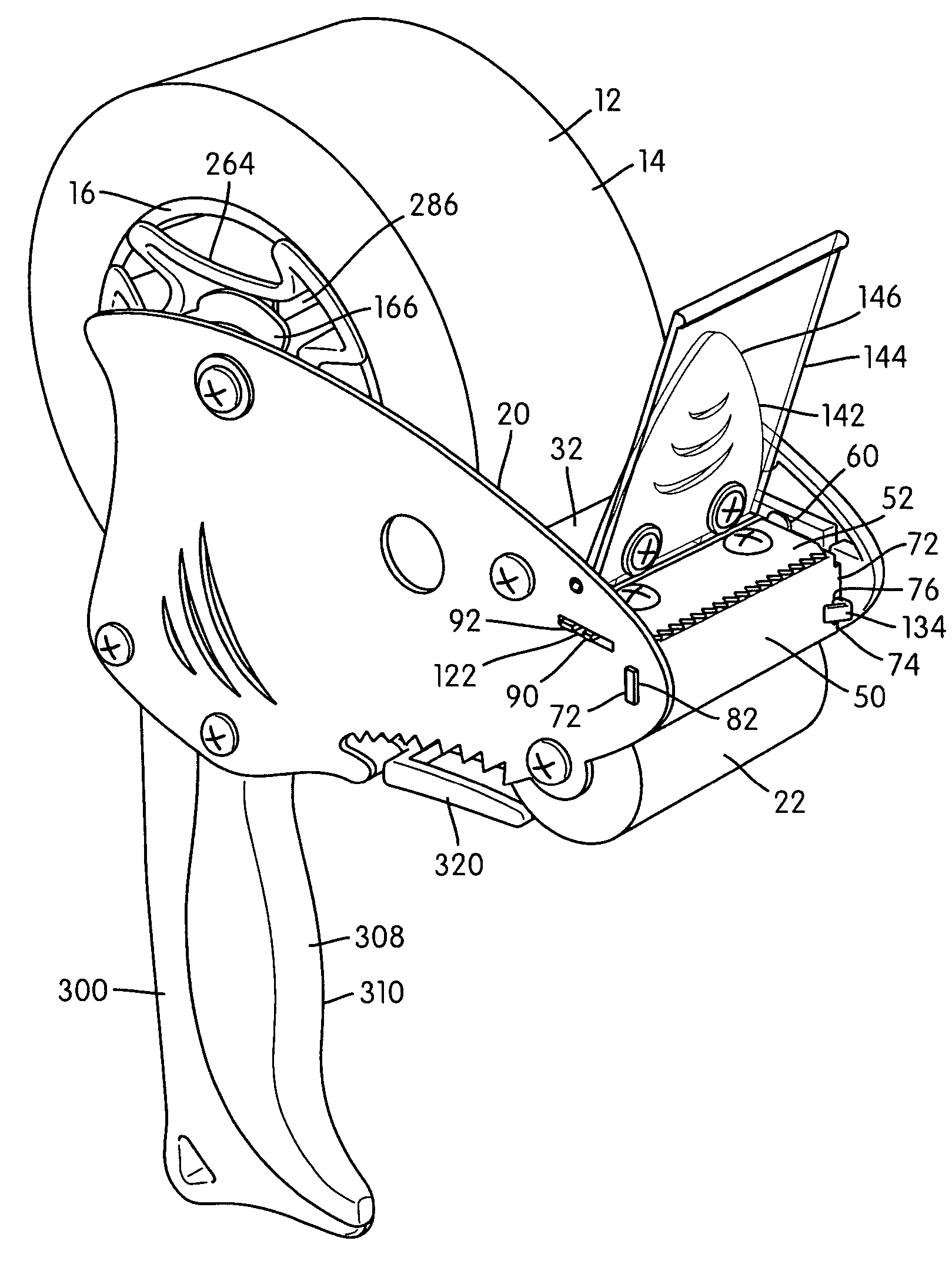
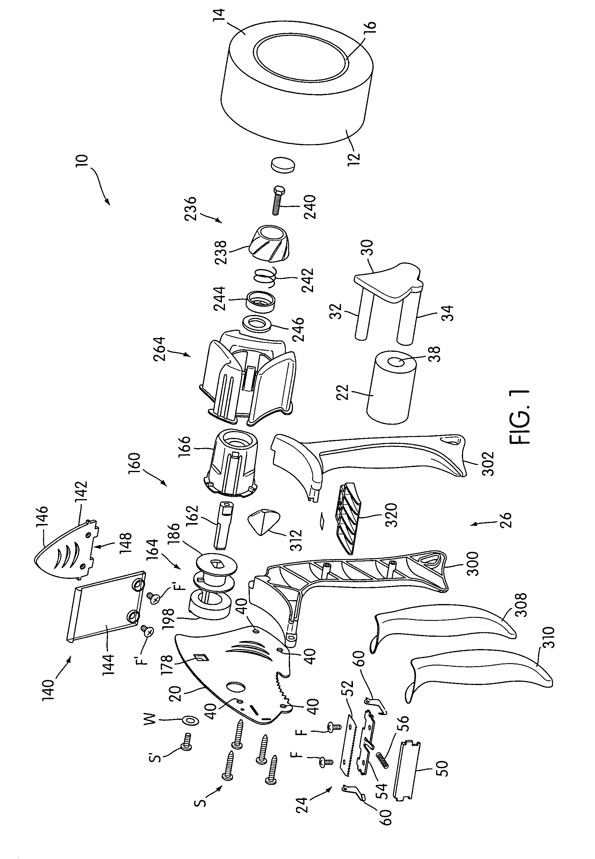
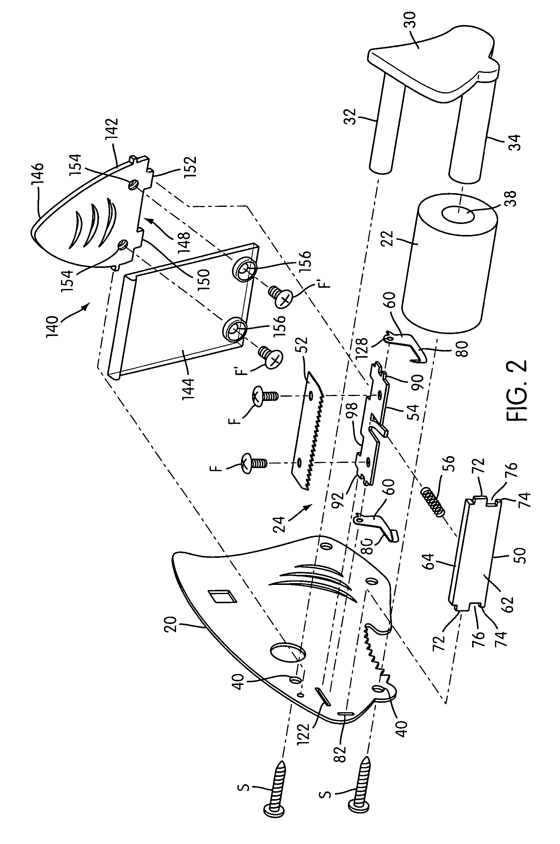
[0035]Referring now to the drawings, wherein the showings illustrate an exemplary embodiment of the present invention only and are not intended to limit same, FIG. 1 shows an adhesive tape dispenser 10 adapted for ergonomic application of adhesive film or tape 12 from a roll 14 onto an application surface (not shown). The tape 12 is typically wound around a cardboard core in a well known manner. The adhesive tape dispenser 10 is particularly useful in dispensing tape wound on a first smaller diameter core (not shown), generally a one inch core, and tape wound on a second larger diameter core 16, generally a three inch core. The adhesive tape dispenser 10 generally includes a frame 20...


PUM

PropertyMeasurementUnit
diameteraaaaaaaaaa
diameteraaaaaaaaaa
adhesiveaaaaaaaaaa

Abstract

A new and improved adhesive tape dispenser is adapted to dispense tape wound upon a tape core and includes a frame, an application roller, a cutter assembly, and handle mounted on the frame. The adhesive tape dispenser includes a core support assembly secured to the frame and having a first axis. The core support assembly comprises a shaft secured to the frame, and an axle assembly disposed about at least a portion of the shaft. A spindle adapted to support the tape core is rotatably mounted on the axle assembly. The axle assembly includes a hub having an outer surface with a second axis adjacent the first axis, at least one flange extending radially from the hub, and a cam rotatably mounted on the hub. The spindle freely rotates in a first direction. Wherein rotation of the spindle in a second direction rotates the cam about the second axis in the second direction whereby the cam engages the spindle preventing further rotation of the spindle in the second direction about the axle assembly.

Description

CROSS REFERENCE TO RELATED APPLICATIONS[0001]This present application is a continuation-in-part of U.S. Design patent application Ser. No. 29 / 202,698 filed Apr. 2, 2004 now U.S. Pat. No. D 520,061, expressly incorporated herein by reference.[0002]The present application further generally relates to the inventions disclosed in commonly owned U.S. patent application Ser. No. 10 / 454,000 filed Jun. 4, 2003; U.S. Design patent application Ser. No. 29 / 178,505 filed Mar. 27, 2003; and U.S. Design patent application Ser. No. 29 / 178,556 filed Mar. 27, 2003.BACKGROUND OF THE INVENTION[0003]The present invention generally relates to a hand-held adhesive tape dispenser.[0004]Conventional hand-held tape dispensers typically include a main body having a handle, a tape reel provided at a rear side of the main body, a roller provided at a front side of the main body, a front plate located above the roller, a blade located above the front plate, and a holding-down plate located above and substantial...

Claims


Application Information

Patent Timeline
Patent Type & Authority Patents(United States)
IPC IPC(8): B65H35/07
CPCB65H35/0033B65H35/0073Y10T156/18Y10T156/1788Y10T156/1795Y10T156/1348B65H2402/412
Inventor BAILEY, CURT J.CHUPA, KRISTEN W.DAUNTER, DOMINIC J.DINGLER, NOAH E. A.HAWLEY, JAMES K.LEAN, MICHAEL B.SOMMERS, SCOTT A.
Owner SHURTAPE TECH LLC
Why Eureka
Try Eureka