
Electric power cable fixing apparatus for an insulator

a technology for fixing apparatus and power cables, which is applied in the direction of insulator conductors, cables, coupling devices, etc., can solve the problems of high manufacturing cost and liability to failure, difficult work fixing power cables on insulators, and weak fixing power, so as to reduce maintenance costs, reduce manufacturing costs, and simple structure

Inactive Publication Date: 2010-03-02
KOREA METAL TECH & MANAGEMENT RES INST +1
View PDF10 Cites 6 Cited by
  • Summary
  • Abstract
  • Description
  • Claims
  • Application Information

AI Technical Summary

Benefits of technology

[0010]In addition, this invention provides a clamping device which can protect the insulation power of insulator by clamping power cable to insulator with latches and fix power cables with diverse diameter firmly.
[0011]In addition, the present invention can prevent corrosion of power cable support base and connector, electric spark by dust, and corona phenomenon, better than binding wire method, by fixing power cable on insulator head with clamping device which clamps and presses power cable to firmly insulator head.
[0012]A further advantage of the power cable fixing apparatus for insulator in accordance with this invention is reduced manufacturing cost due to the simple structure using less number of parts, and reduced maintenance cost because the apparatus in accordance with this invention is free from crack and blooming which may occur in the industrial zones subject to higher concentration of ozone and sea shore regions subject to higher salt concentration in the air.

Problems solved by technology

However, this technology comprises many parts in complicate structure which leads to higher manufacturing cost and liability to failure, and the work fixing power cable on an insulator is not easy.
However, though this technology provides easy workability with simple structure consisted of a fixing hole in the insulator and a binder wire, the fixing power is very weak because power cable is held with a single strand of binder wire and the device may damage the surface of power cable and fittings.

Method used


Image

  • Electric power cable fixing apparatus for an insulator
  • Electric power cable fixing apparatus for an insulator
  • Electric power cable fixing apparatus for an insulator

Examples


Embodiment Construction

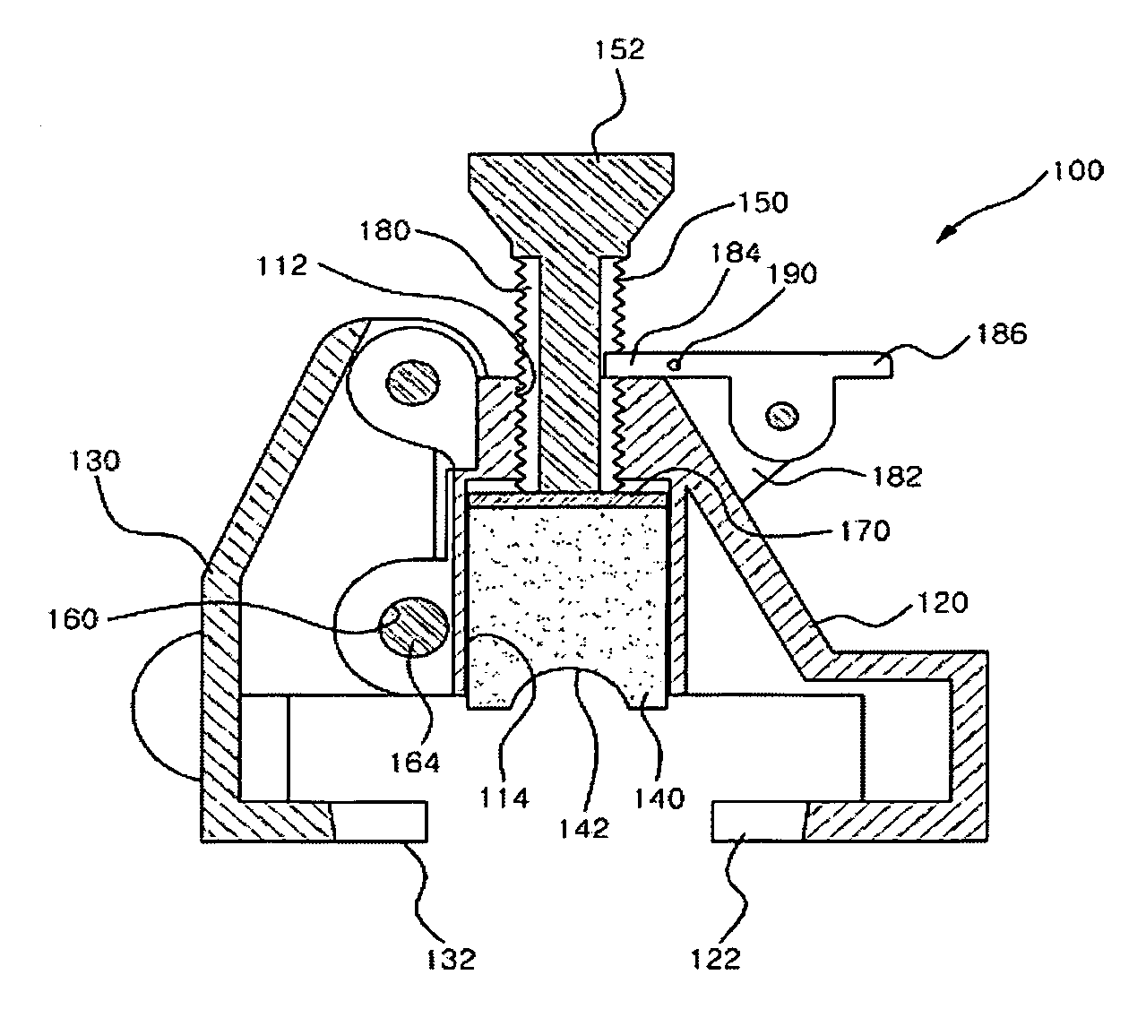
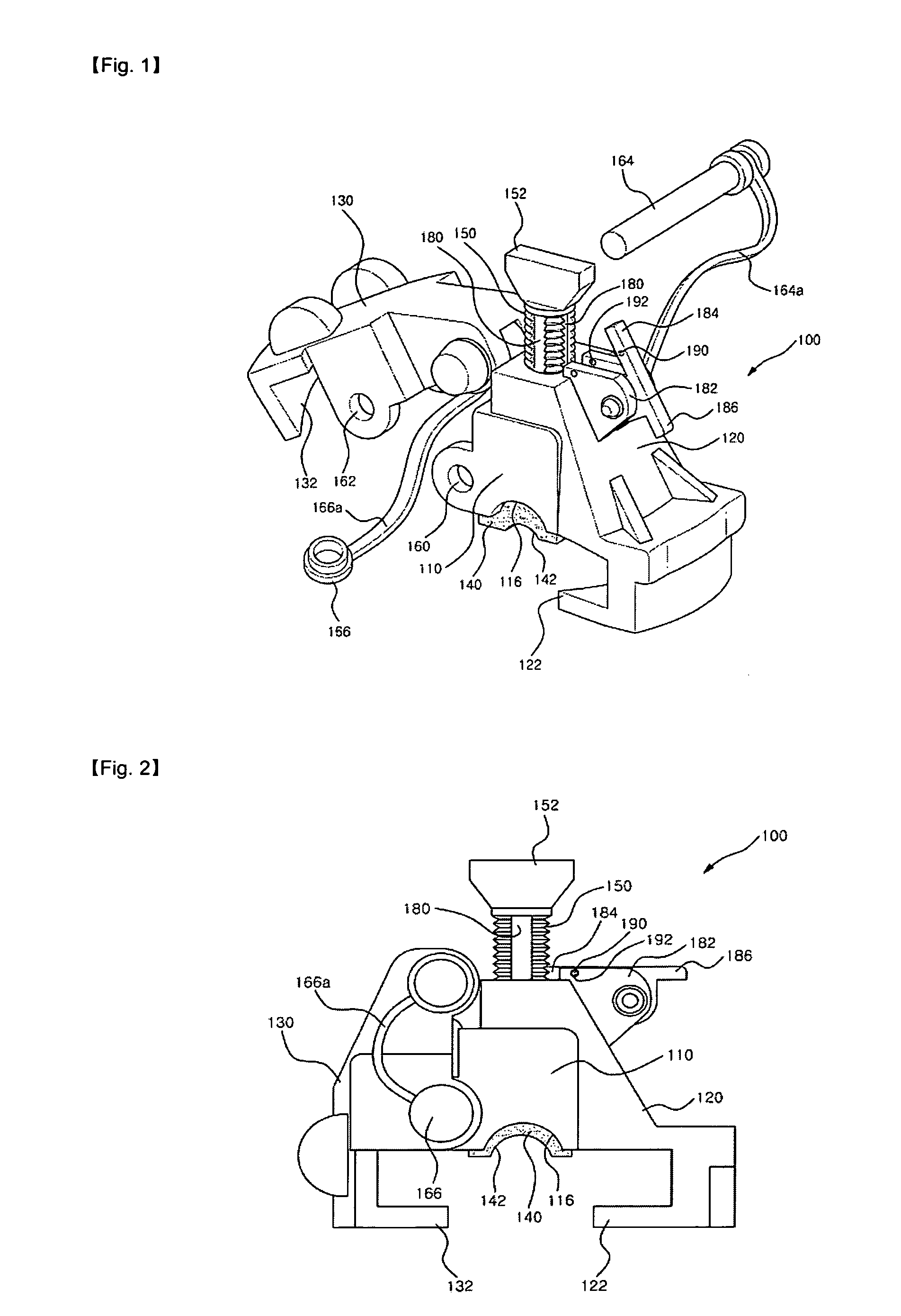
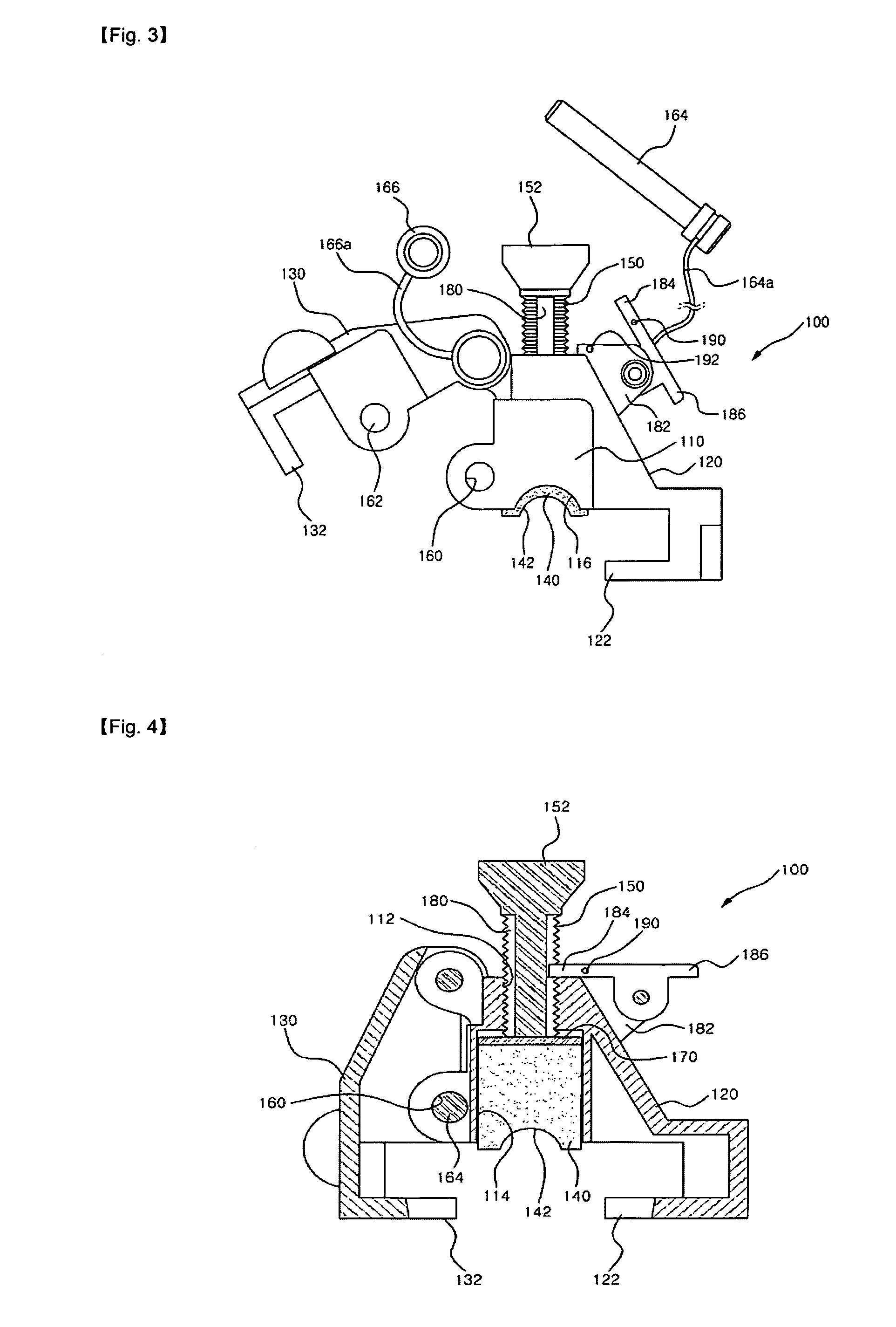
[0024]In order to achieve aforementioned purposes, the power cable fixing apparatus for insulator in accordance with this invention comprises; the main body which is formed with a through bolt hole in the center part, and the bolt hole is formed with a space of a certain size and the bottom of the space is open and is formed with round power cable groove; a fixed clamp formed on one side of said main body with a latch at the bottom to hook insulator head; a movable clamp formed on the opposite side of said main body with a latch at the bottom to hook the other side of the insulator head, rotatable in a vertical plane; an elastic holding member formed on the space part of said main body, movable in vertical direction, with a groove on the bottom to hold upper part of power cable; a fixing bolt engaged in the bolt hole of the main body, pressing the elastic holding member by screwing inward, so that the power cable can be fixed between the holding groove on top of the insulator and th...


PUM


Abstract

An apparatus fixing a power cable to an insulator, which clamps the head of the insulator to fix the power cable to an insulator head, easily and firmly. To this end, the apparatus includes a main body formed with a vertical through bolt hole in the center, with a space, formed beneath the bolt hole, with a round open bottom which holds the power cable; a fixed clamp formed on one side of the main body with a latch at the bottom to hook the insulator head; a movable clamp formed on the opposite side of the main body with a latch at the bottom to hook the other side of the insulator head; a movable, elastic holding member formed on the space part of the main body, with a groove on the bottom to hold upper part of the power cable; a fixing bolt engaged in the bolt hole of the main body, pressing the elastic holding member by screwing inward, so that the power cable can be fixed between the holding groove on top of the insulator and the holding groove on the bottom of the elastic holding member; and a movable clamp fixing member to fix the movable clamp engaged with the insulator head.

Description

BACKGROUND OF THE INVENTION[0001]This invention relates to a power cable fixing apparatus for insulator, in more detail, an apparatus which can fix power cable on top of an insulator easily and firmly, without limitation in the applicable diameter of the cable, improving the insulation power of the insulator.[0002]In general, the electric power generated in power plants is transmitted through high voltage power line and distributed to end users. Power cables are installed in various ways from power plants to end users, through underground or above ground. The power cables installed above ground are usually installed on poles. According to the method of supporting power cables on poles, the poles are erected at certain intervals to support power cables stably.[0003]The pole and the power cable are electrically insulated with an insulator which is mounted on a support installed on the pole, in order to prevent the electric current from flowing from the power cable to the pole.[0004]In...

Claims


Application Information

Patent Timeline
Patent Type & Authority Patents(United States)
IPC IPC(8): H02G7/00
CPCH01B17/16H02G7/053H01B17/06
Inventor AN, BYUNG-JUNAN, JEOM-DONG
Owner KOREA METAL TECH & MANAGEMENT RES INST
Learn More