Substrate treatment apparatus

a technology of substrate and treatment apparatus, which is applied in the direction of chemical vapor deposition coating, multiple-port network, coating, etc., can solve the problem of damage to the high-voltage dc power supply

Active Publication Date: 2019-10-08
ASM IP HLDG BV
View PDF10 Cites 2 Cited by
  • Summary
  • Abstract
  • Description
  • Claims
  • Application Information

AI Technical Summary

Benefits of technology

[0006]The present invention has been made to solve the above-described problem and it is an object of the present invention to provide a substrate treatment apparatus capable of protecting an electrostatic chuck DC power supply from AC power.

Problems solved by technology

However, there is a problem that the above-described AC power may cause damage to the high voltage DC power supply.

Method used


Image

  • Substrate treatment apparatus
  • Substrate treatment apparatus
  • Substrate treatment apparatus

Examples


first embodiment

(Substrate Treatment Apparatus )

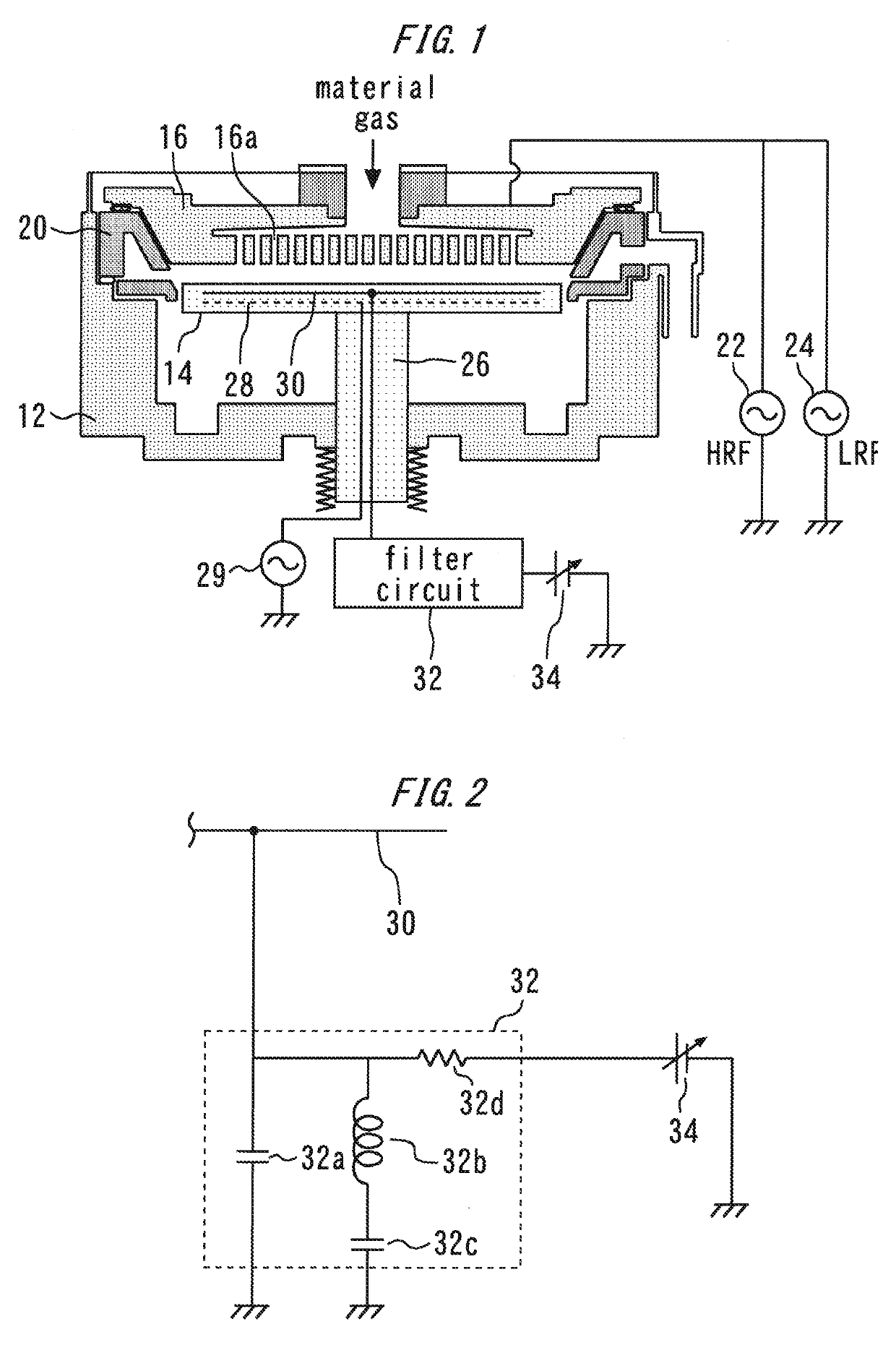
[0032]The first embodiment of the present invention provides the filter circuit capable of passing AC power at HRF and LRF to the ground. Therefore, it is possible to provide the filter circuit 32 that functions as a filter that grounds the AC power at the first frequency and the AC power at the second frequency without increasing the size of the capacitor as in the case of the comparative example. By providing the filter circuit 32, it is possible to normally generate discharge between the upper electrode 16 and the lower electrode 14 and also protect the DC power supply 34 provided for an electrostatic chuck from AC power.

(Modification)

[0033]The substrate treatment apparatus according to the first embodiment of the present invention can be modified in various ways without losing its features. By providing the capacitor 32a as the first filter circuit, it is possible to pass AC power at the first frequency at, for example, approximately 13.56 MHz in ...

second embodiment

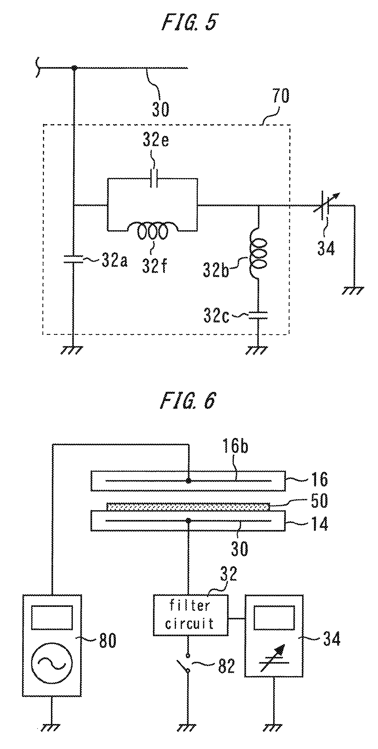
[0035]FIG. 5 is a diagram illustrating a filter circuit 70 of a substrate treatment apparatus according to a second embodiment. The filter circuit 70 is provided with a third filter circuit composed of a parallel circuit of a capacitor 32e and an inductor 32f The third filter circuit is provided between the internal electrode 30 and the DC power supply 34 by avoiding a path connecting the internal electrode 30 and the capacitor 32a which is the first filter circuit. That is, the third filter circuit is connected to a wiring which is branched from the wiring that connects the internal electrode 30 and the capacitor 32a.

[0036]The third filter circuit is formed so as to become low impedance with respect to AC power at the second frequency and become high impedance with respect to AC power at the first frequency. That is, the third filter circuit functions as a high-cut filter. Suppose a case where a capacitance of the capacitor 32e is 100 pF and an inductance L of the inductor 32f is ...

third embodiment

[0038]FIG. 6 is a diagram illustrating a substrate treatment apparatus according to a third embodiment. An AC power supply 80 supplies AC power to the internal electrode 16b of the upper electrode 16. The DC power supply 34 is connected to the internal electrode 30 via the filter circuit 32. The internal electrode 30 is provided in the lower electrode 14. The DC power supply 34 applies a voltage to the internal electrode 30, and thereby provides an electrostatic chuck.

[0039]A switch 82 can switch connection or disconnection between the internal electrode 30 and the ground. The switch 82 connects the internal electrode 30 to the ground for a period during which treatment is applied to the substrate and keeps the internal electrode 30 disconnected from the ground for other periods. Therefore, the period during which plasma is generated and treatment is applied to the substrate, AC power applied to the upper electrode 16 flows to the ground via both the filter circuit 32 and the switch...


PUM

PropertyMeasurementUnit
frequencyaaaaaaaaaa
frequencyaaaaaaaaaa
frequencyaaaaaaaaaa

Abstract

A substrate treatment apparatus includes a lower electrode, an upper electrode, a first AC power supply that is connected to the upper electrode and supplies AC power at a first frequency, a second AC power supply that is connected to the upper electrode and supplies AC power at a second frequency which is lower than the first frequency, an internal electrode provided in the lower electrode, a filter circuit connected to the internal electrode, and a DC power supply connected to the internal electrode via the filter circuit. The filter circuit includes a first filter circuit that becomes low impedance with respect to AC power at the first frequency compared to AC power at the second frequency, and a second filter circuit that becomes low impedance with respect to AC power at the second frequency compared to AC power at the first frequency.

Description

BACKGROUND OF THE INVENTION[0001]Field of the Invention[0002]The present invention relates to a substrate treatment apparatus used for substrate treatment such as film formation.[0003]Background Art[0004]U.S. Pat. No. 5,366,585 discloses a film formation apparatus provided with a plasma treatment reaction chamber.[0005]There are substrate treatment apparatuses that generate plasma between a lower electrode and an upper electrode by supplying AC power to the upper electrode while supplying a material gas to between the lower electrode and the upper electrode, and apply treatment to a substrate on the lower electrode. Such substrate treatment apparatuses require a high voltage DC power supply that applies a voltage to the lower electrode to suck the substrate to the lower electrode using an electrostatic chuck. However, there is a problem that the above-described AC power may cause damage to the high voltage DC power supply.SUMMARY OF THE INVENTION[0006]The present invention has been ...

Claims


Application Information

Patent Timeline
Patent Type & Authority Patents(United States)
IPC IPC(8): H01L21/00C23C16/00C23C16/50H01J37/00H01L21/683C23C16/503
CPCC23C16/503C23C16/50H01L21/6833H01J37/00C23C16/513H01J37/20H01J37/32697H01J37/32165H01J37/32183H01J37/32532H03H7/38H01J37/32522
Inventor TSUJI, NAOTOSUGURI, TAKUYAIKEDO, YOZO
Owner ASM IP HLDG BV
Why Eureka
Try Eureka