
Electronic device and power protection method

a technology of electronic devices and power protection, applied in the direction of emergency protective arrangements for limiting excess voltage/current, circuit arrangements, arrangements responsive to excess voltage, etc., can solve problems such as permanent damage to electronic devices, and achieve the effect of improving reliability and safety of the internal core circuit of the electronic device and providing power protection

Active Publication Date: 2016-05-05
ASUSTEK COMPUTER INC
View PDF11 Cites 2 Cited by
  • Summary
  • Abstract
  • Description
  • Claims
  • Application Information

AI Technical Summary

Benefits of technology

The patent text describes a feature in an electronic device that prevents damage when an external device is plugged in or out. This improves the reliability and safety of the electronic device's internal circuitry.

Problems solved by technology

When the external device is plugged in / out a transfer port of the electronic device, inrush current caused by a transient voltage change is generated on the transfer port of the electronic device and thus damage the electronic device permanently.

Method used


Image

  • Electronic device and power protection method
  • Electronic device and power protection method
  • Electronic device and power protection method

Examples


Embodiment Construction

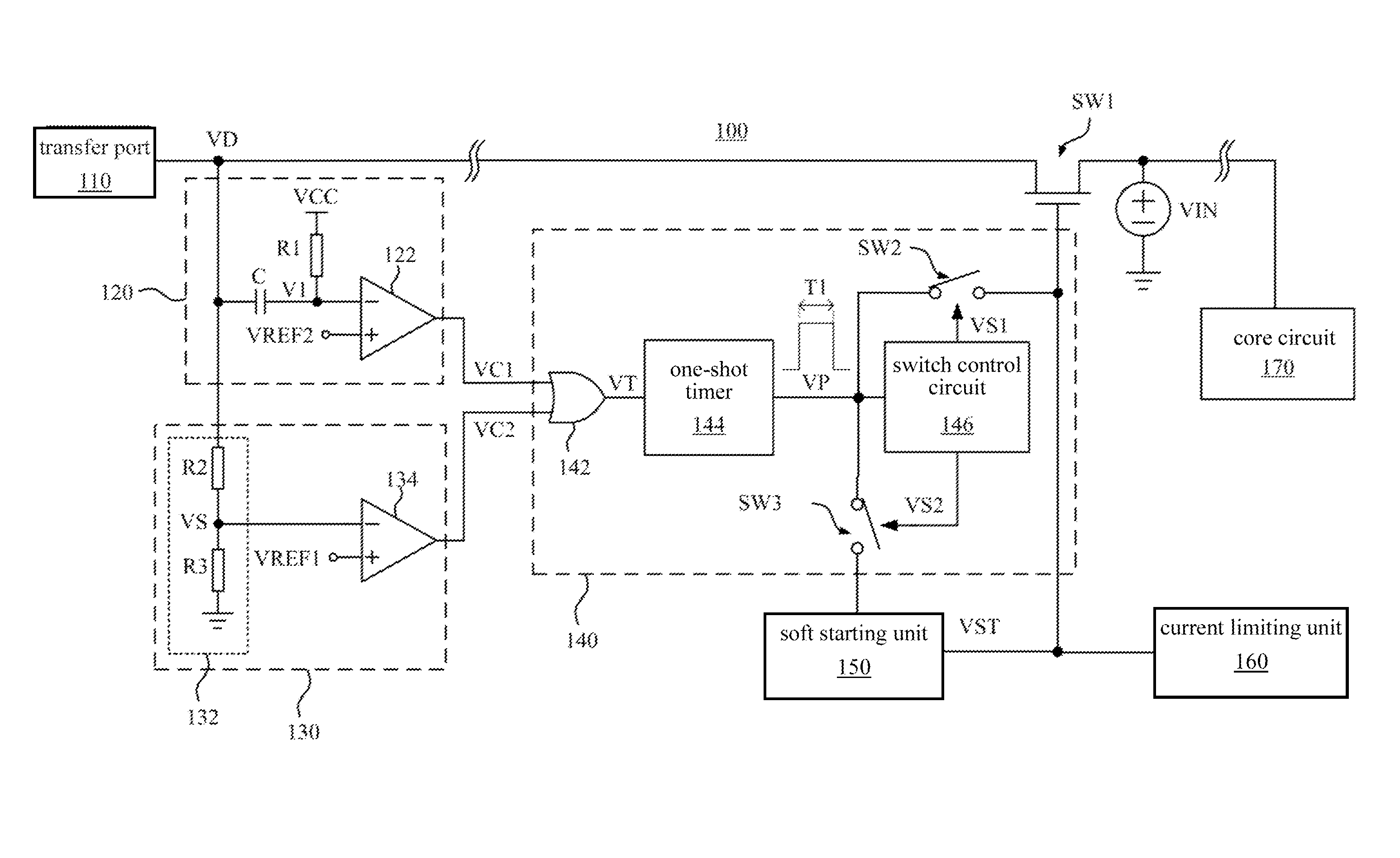
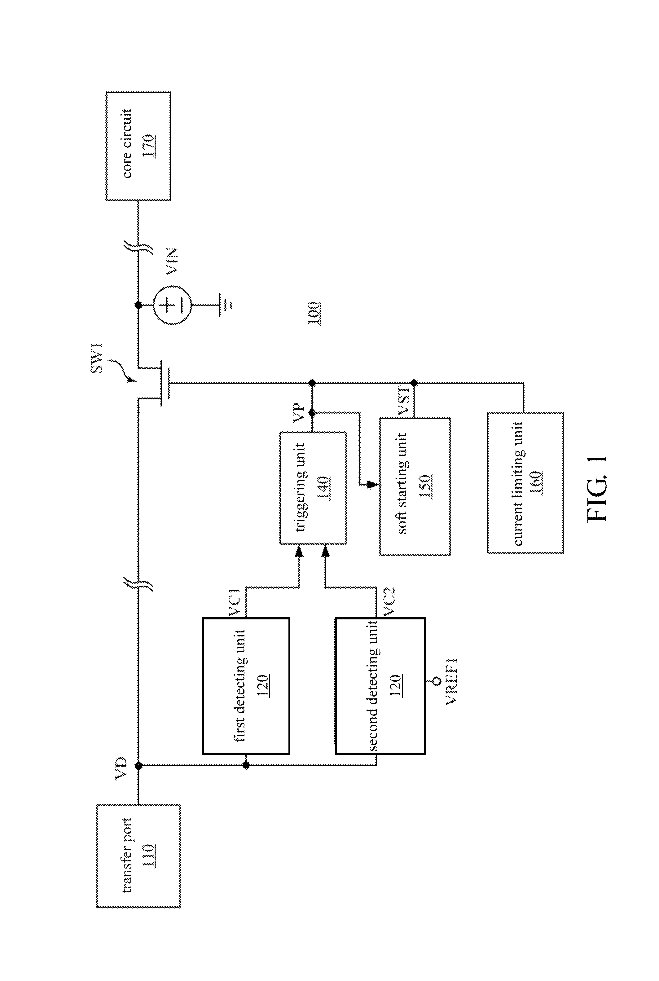
[0016]FIG. 1 is a schematic diagram showing an electronic device in an embodiment. In an embodiment, an electronic device 100 is an electronic product, such as a personal computer, a laptop, a tablet computer, a smart phone, which is not limited herein.

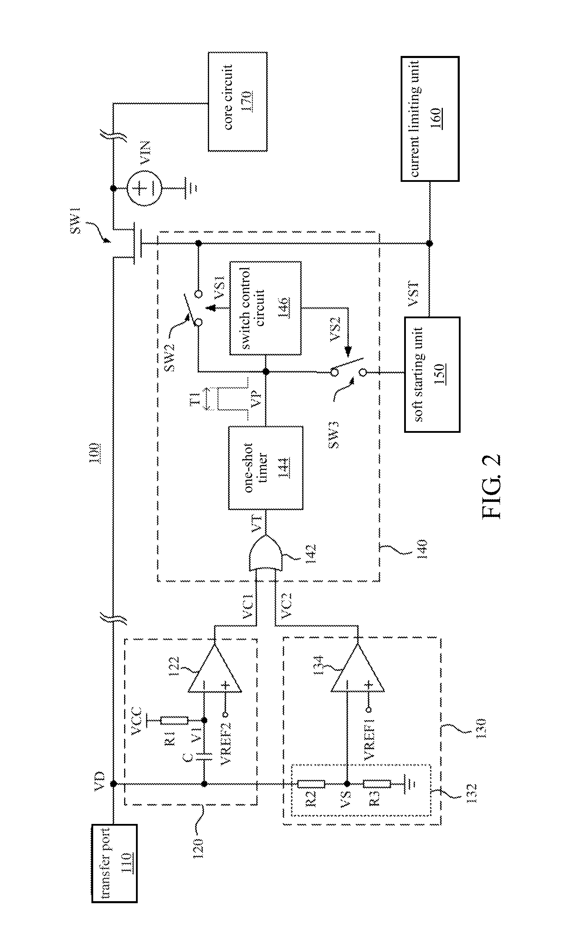
[0017]As shown in FIG. 1, the electronic device 100 includes a transfer port 110, a first switch SW1, a first detecting unit 120, a second detecting unit 130, a triggering unit 140, a soft starting unit 150, a current limiting unit 160 and a core circuit 170.

[0018]The transfer port 110 is used to provide a driving voltage VD to an external device. In an embodiment, the transfer port 110 is a bus, such as a universal serial bus (USB), micro USB, which is not limited herein. The core circuit 170 includes a processor and / or a control chip of the system, which is not limited herein.

[0019]As shown in FIG. 1, the first detecting unit 120 generates a first control signal VC1 when a voltage drop of the driving voltage VD exceeds a threshold v...


PUM


Abstract

An electronic device and a power protection method are provided. The electronic device includes a transfer port, a switch, a first detecting unit and a second detecting unit. The transfer port provides a driving voltage to an external device. The switch is coupled between the transfer port and a supply power source, and the switch is selectively turned off according to at least one of a first control signal and a second control signal. The first detecting unit generates the first control signal when a voltage drop of the driving voltage exceeds a threshold voltage. The second detecting unit generates a sampling voltage by detecting the driving voltage and generates the second control signal when the sampling voltage is lower than a first reference voltage. The electronic device can provide a power protection when an external device is plugged in / out the transfer port.

Description

CROSS-REFERENCE TO RELATED APPLICATION[0001]This application claims the priority benefit of China application serial No. 201410598937.3, filed on Oct. 30, 2014. The entirety of the above-mentioned patent application is hereby incorporated by references herein and made a part of specification.BACKGROUND OF THE INVENTION[0002]1. Field of the Invention[0003]The disclosure relates to an electronic device and, more particularly, to an electronic device with a power protection.[0004]2. Description of the Related Art[0005]In general, a variety of transport interfaces are disposed at consumer electronic devices for connecting to an external device for transferring data and charging.[0006]When the external device is plugged in / out a transfer port of the electronic device, inrush current caused by a transient voltage change is generated on the transfer port of the electronic device and thus damage the electronic device permanently.BRIEF SUMMARY OF THE INVENTION[0007]An electronic device inclu...

Claims


Application Information

Patent Timeline
Patent Type & Authority Applications(United States)
IPC IPC(8): H02H3/20H05B44/00
CPCH02H3/20H02H3/207H02H9/001
Inventor ZHOU, XIAO-FENGHAN, WEILIANG, CHING-JI
Owner ASUSTEK COMPUTER INC
Learn More