Waste-heat recovery system

a technology of waste heat and recovery system, which is applied in the direction of liquid degasification, electric generator control, separation process, etc., can solve the problems of low temperature level heat, frequent inability to use heat having a low temperature level, and poor charge of the cylinder otherwis

Inactive Publication Date: 2014-01-02
ROBERT BOSCH GMBH
View PDF4 Cites 2 Cited by
  • Summary
  • Abstract
  • Description
  • Claims
  • Application Information

AI Technical Summary

Benefits of technology

[0019]Using the present invention, the design and the operating behavior of a waste-heat recovery plant composed of an ORC downstream from a waste-heat source, is optimized. Waste-heat sources may be, for example, combined heat and power plants, industrial plants or boiler plants. The measures according to the present invention protect the expansion machine from power outages or keep it in a safe operating state under such an operating condition.

Problems solved by technology

Since water evaporates at 100° C. under atmospheric conditions, it is frequently impossible to use heat having a low temperature level, e.g., industrial waste heat or earth heat, to generate power.
Cooling of the combustion-gas mixture is generally required because the charge of the cylinder would otherwise be relatively poor.

Method used


Image

  • Waste-heat recovery system
  • Waste-heat recovery system

Examples


Embodiment Construction

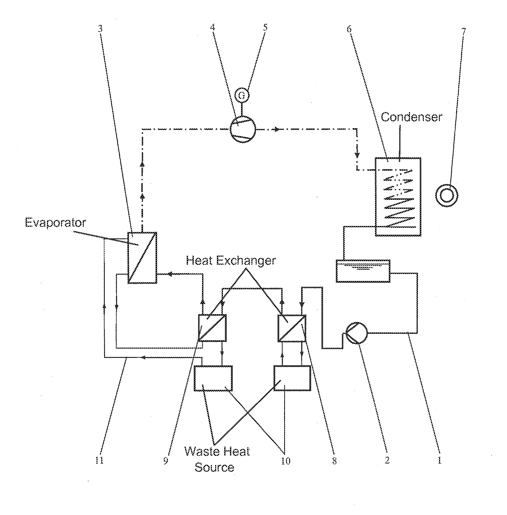
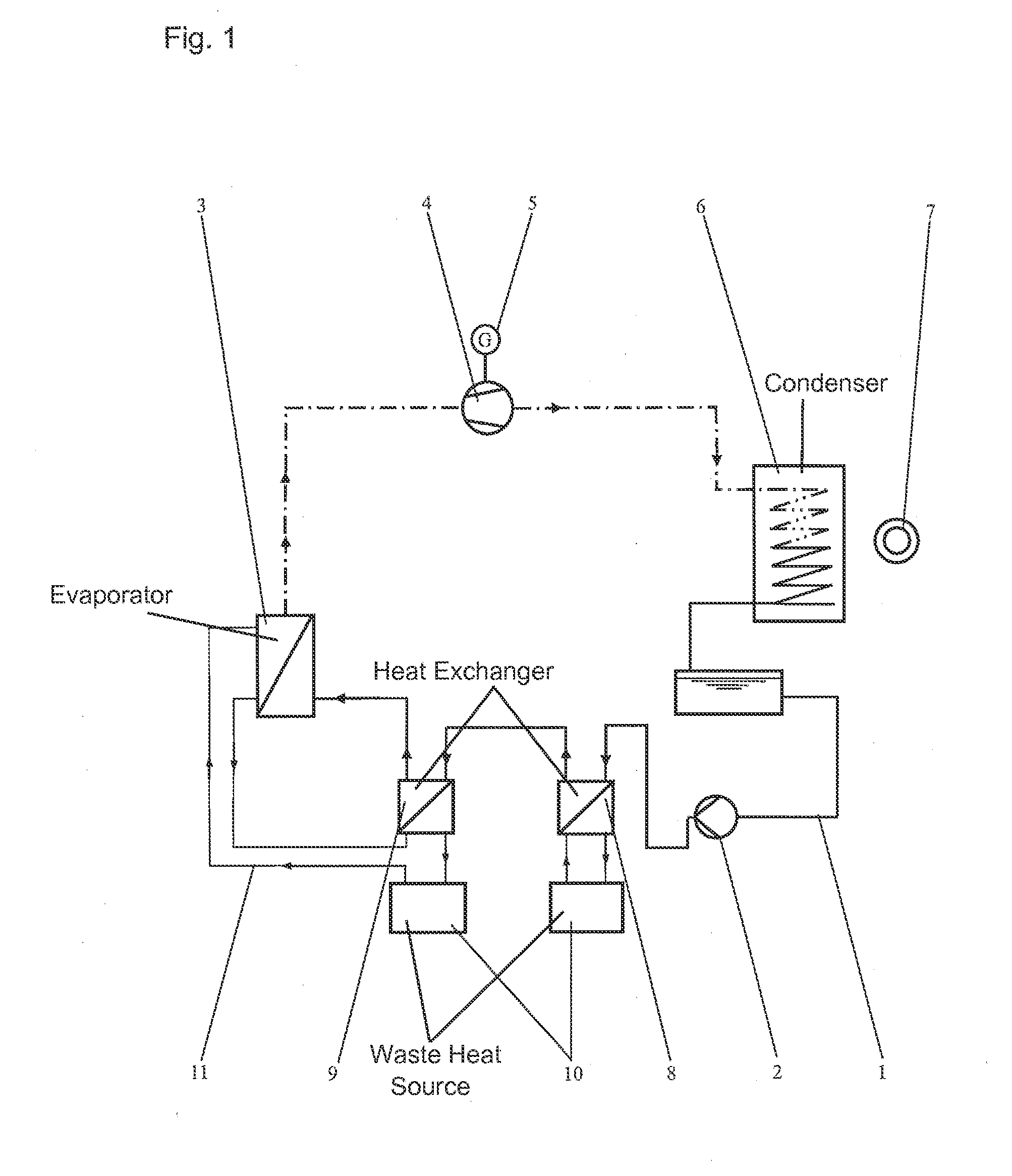
[0021]The components that operate the ORC are an ORC circulation circuit 1, a feeding pump 2, an evaporator 3, an expansion machine 4 for vapor expansion, which is coupled to a generator 5, a condenser 6 for recooling via a heat sink 7, and heat exchangers 8, 9 for preheating the working medium in ORC circulation system 1.

[0022]The two heat exchangers 8, 9 are connected in series downstream from feeding pump 2. First heat exchanger 8 downstream from feeding pump 2 is used as the first stage for incoupling of the low-temperature heat, and following heat exchanger 9 is used as a second stage for incoupling of the high-temperature heat from a waste-heat source 10.

[0023]A second heating circuit 11, via its supply region, is connected to evaporator 3 of the ORC, because the temperature level is initially sufficiently high for its direct heating. After that, second heating circuit 11 discharges into second heat exchanger 9 on the return side, where it releases still existing residual heat...


PUM

PropertyMeasurementUnit
temperatureaaaaaaaaaa
electric energyaaaaaaaaaa

Abstract

A waste-heat recovery system for a waste-heat source, made up of an ORC (Organic-Rankine Cycle) postconnected thereto. The waste-heat source is connected with the heating device of the ORC as well as an expansion machine, coupled to a generator, for steam expansion in the ORC, which has magnetic bearings with an associated control device and a power supply via a direct current intermediate circuit of a generator frequency converter. The design and safe operating behavior of a waste-heat recovery system made up of an ORC post-connected to a waste-heat source are optimized. In a power supply failure, the electric energy that a down-running generator continues to generate is used to supply the magnetic bearings with the associated control device in order to ensure a safe operation in the event of a power supply failure.

Description

FIELD OF THE INVENTION[0001]The present invention relates to a waste-heat recovery system.BACKGROUND INFORMATION[0002]An ORC (Organic-Rankine Cycle) is a thermodynamic cyclical process according to Rankine. This means that a working medium runs through various thermodynamic states in order to be transferred back into the initial liquid state again at the end. In the process, the working medium is brought to a higher pressure level with the aid of a pump. Then, the working medium is preheated to evaporation temperature and subsequently evaporated.[0003]Thus, it is an evaporation process, in which an organic medium instead of water is evaporated. The created steam drives an expansion machine, e.g., a turbine, a piston or propeller motor, which in turn is coupled to an electric generator in order to generate power. Downstream from the working machine, the process medium enters a condenser where it is cooled down again through heat dissipation. Since water evaporates at 100° C. under at...

Claims


Application Information

Patent Timeline
Patent Type & Authority Applications(United States)
IPC IPC(8): H02K7/18F01K13/02
CPCH02K7/1823F01K13/02F01K23/065F01K25/10F01K23/06
Inventor TEMELCI-ANDON, ANAYETHERRMANN, KONRADMULLER, STEFANKOHILLER, HARALD
Owner ROBERT BOSCH GMBH
Why Eureka
Try Eureka