Structure of a circuit board for improving the performance of routing traces
a circuit board and routing trace technology, applied in the direction of printed circuit aspects, high frequency circuit adaptations, metallic pattern materials, etc., can solve the problems of severe elimination of the performance and frequency response of routing trace in a pcb, complicated circuit board design, and resonant effect, so as to improve the performance of routing trace, eliminate the resonant effect, and improve the effect of routing trace respons
- Summary
- Abstract
- Description
- Claims
- Application Information
AI Technical Summary
Benefits of technology
Problems solved by technology
Method used
Image
Examples
first embodiment
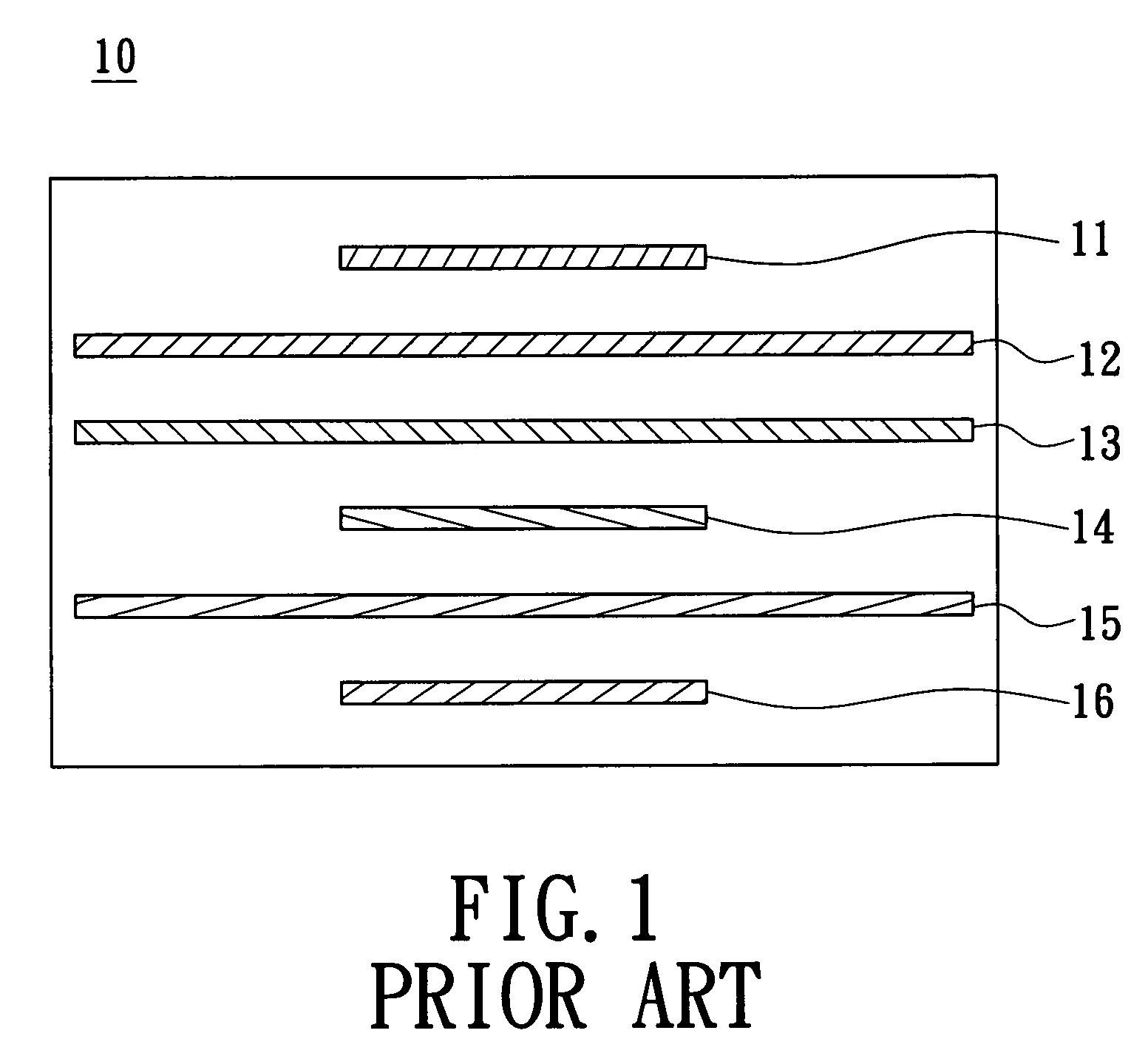
[0029]FIG. 4 shows the structure of a circuit board 100 in the present invention. The etching hole 50 shown in this drawing covers the above routing trace 65 entirely, in which the routing trace 65 is made of metal fine trace, whose width can be designed or the thickness of electric layer of routing trace 65 can be increased as the characteristic impedance requires. Moreover, the size of area of the etching hole 50 next to the routing plane 60 also can be designed to or not to link with the via hole 45, and the routing plane 60 can connect to the power plane 40 and ground plane 20 via conductive plugs inside these via hole 45. Accordingly, to provide a better frequency response, the invention provides different embodiments for any specific case.
[0030]Since the area of the routing trace on a circuit board is insufficient, the other routing traces should set on the other side or the inner layer of the circuit board as are the six layers shown in FIG. 5, which illustrates the second em...
third embodiment
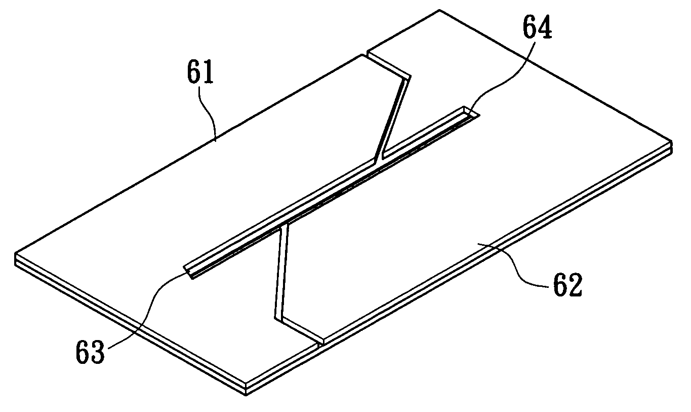
[0031]the circuit board structure in the present invention is illustrated in FIG. 6. There are probably many power sets with different voltages on power plane, and which are divided into the first power plane 61 and second power plane 62 shown in FIG. 6 by one or a plurality of etching slots 63, especially in the manufacturing process of microchip. Several power sets including first power plane 61 and second power plane 62 on power plane are divided by etching slot 63 with any shape, so the routing trace 64 in the under layer can make electric potential reference to the ground plane. In practice, the width of the etching slot 63 is not five times smaller than the width of the routing trace 64.
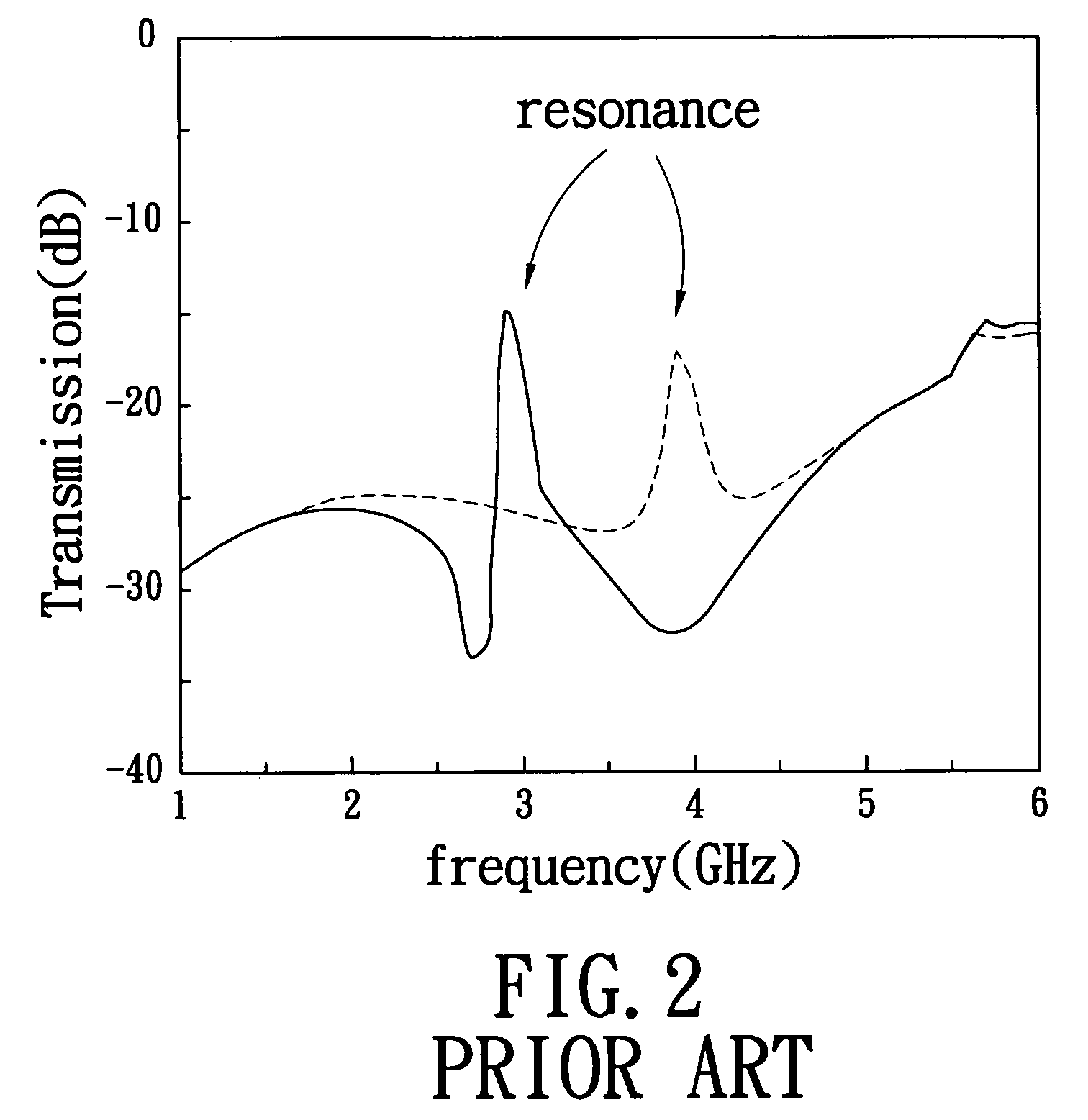
[0032]The schematic diagram of the experimental results of the frequency response is shown in FIG. 7, which shows the smoother curve around the previous peaks of 2.9 GHz and 3.9 GHz. It shows the result of effectively reducing the resonance effect and parasitic resonance in the prior art. The s...
PUM
 Abstract
Description
Claims
Application Information
 - R&D
- Intellectual Property
- Life Sciences
- Materials
- Tech Scout
- Unparalleled Data Quality
- Higher Quality Content
- 60% Fewer Hallucinations
Browse by: Latest US Patents, China's latest patents, Technical Efficacy Thesaurus, Application Domain, Technology Topic, Popular Technical Reports.
© 2025 PatSnap. All rights reserved.Legal|Privacy policy|Modern Slavery Act Transparency Statement|Sitemap|About US| Contact US: help@patsnap.com


