Brush bag for a dynamo-electric machine

a dynamo-electric machine and current transfer technology, which is applied in the direction of dynamo-electric machines, current collectors, line/current collector details, etc., can solve the problems of reducing reducing the use value of the brush, and reducing the wear of the brush. , to achieve the effect of extending the life of the brush, and reducing the wear of the brush

Inactive Publication Date: 2010-03-02
BSH BOSCH & SIEMENS HAUSGERAETE GMBH
View PDF16 Cites 2 Cited by
  • Summary
  • Abstract
  • Description
  • Claims
  • Application Information

AI Technical Summary

Benefits of technology

[0019]According to an advantageous further development, the inwardly directed formations of the front guiding area are embodied in the form of at least one bead and / or at least one knob. Such configurations can be produced particularly simply, for example by embossing. In this embodiment of the brush bag it is also advantageous that a relatively large play or distance between the brush and the brush bag is possible in the immediate vicinity outside the front guiding area of the brush bag thus formed. Consequently, brush dust particles which enter between the brush and brush bag can easily escape again.
[0020]In a further advantageous embodiment of the invention, the brush bag has a high-resistance or electrically non-conducting layer in the front guiding area. Any formation of shunt currents in the brush is avoided by such a layer. This has the result that the brush wear can be reduced during operation of the dynamo-electric machine and consequently the lifetime of the brush can be extended. In known insulated brush bags, such a layer extends over the entire guiding area of a brush bag. In contrast, a brush bag according to the further development of the invention can be produced more cost-effectively than the brush bags known hitherto since only the front guiding area of the brush bag has an electrically non-conducting layer.
[0021]The invention also relates to a brush for use in the brush bag according to the invention. The advantageous embodiment of the brush is characterised in that areas of the brush which can come in contact with the front guiding area during an intended use for operating a dynamo-electric machine, have a high-resistance or electrically non-conducting layer. Such a layer can prevent the formation of shunt currents. Since only partial areas of the brush need to have the electrically non-conducting layer, insulating material can be saved compared with brushes coated over the full area.
[0022]In an advantageous further development of the invention, the electrically non-conducting layer consists of an insulating varnish. Such a varnish can be simply applied to the brush, making the brush only insignificantly more expensive.
[0023]The invention further relates to a current transfer unit which advantageously contains at least one brush bag according to the invention and / or a brush according to the invention. The invention also relates to a dynamo electric machine comprising such a current transfer unit, a brush bag according to the invention and / or a brush according to the invention. Such a current transfer unit or such a dynamo electric machine in the form of an AC universal motor can be used particularly advantageously in a washing machine since these devices must be operated with low noise, wherein components which are as inexpensive as possible, for example, a drive motor with a current transfer unit according to the invention, are used to produce the washing machine.
[0024]The invention further relates to a method for manufacturing a brush bag according to the invention, wherein in addition to a step for producing a brush bag, the method advantageously comprises a further step in which the brush bag is after-pressed or embossed in an area of the front guiding area so as to form a brush bag wherein the distance from a brush to be guided in at least one longitudinal extension located transverse to the brush in a front guiding area of the brush bag is shorter than in a rear guiding area.

Problems solved by technology

Whilst the brush is used as prescribed, the brush undergoes wear whereby it is abraded.
A disadvantage with the large play is that noise is produced during operation of the dynamo electric machine.
A disadvantage with the small play is that the brush dust which enters into the intermediate space can deposit in the intermediate space whereby the brush jams in the brush bag or the layers of the brush are short-circuited by unburned brush dust.
In addition, such an insulating layer cannot be subjected to such strong thermal and mechanical loading as a pure metal guide.
A disadvantage with this design however is that the spring provided to track the brush inside the brush holder must have a significantly higher spring force than is the case in embodiments which provide a play between the brush and the brush holder.
However, the spring force required to overcome the friction between the brush and the brush holder can result in higher wear of the brush on the commutator.

Method used


Image

  • Brush bag for a dynamo-electric machine
  • Brush bag for a dynamo-electric machine
  • Brush bag for a dynamo-electric machine

Examples


Embodiment Construction

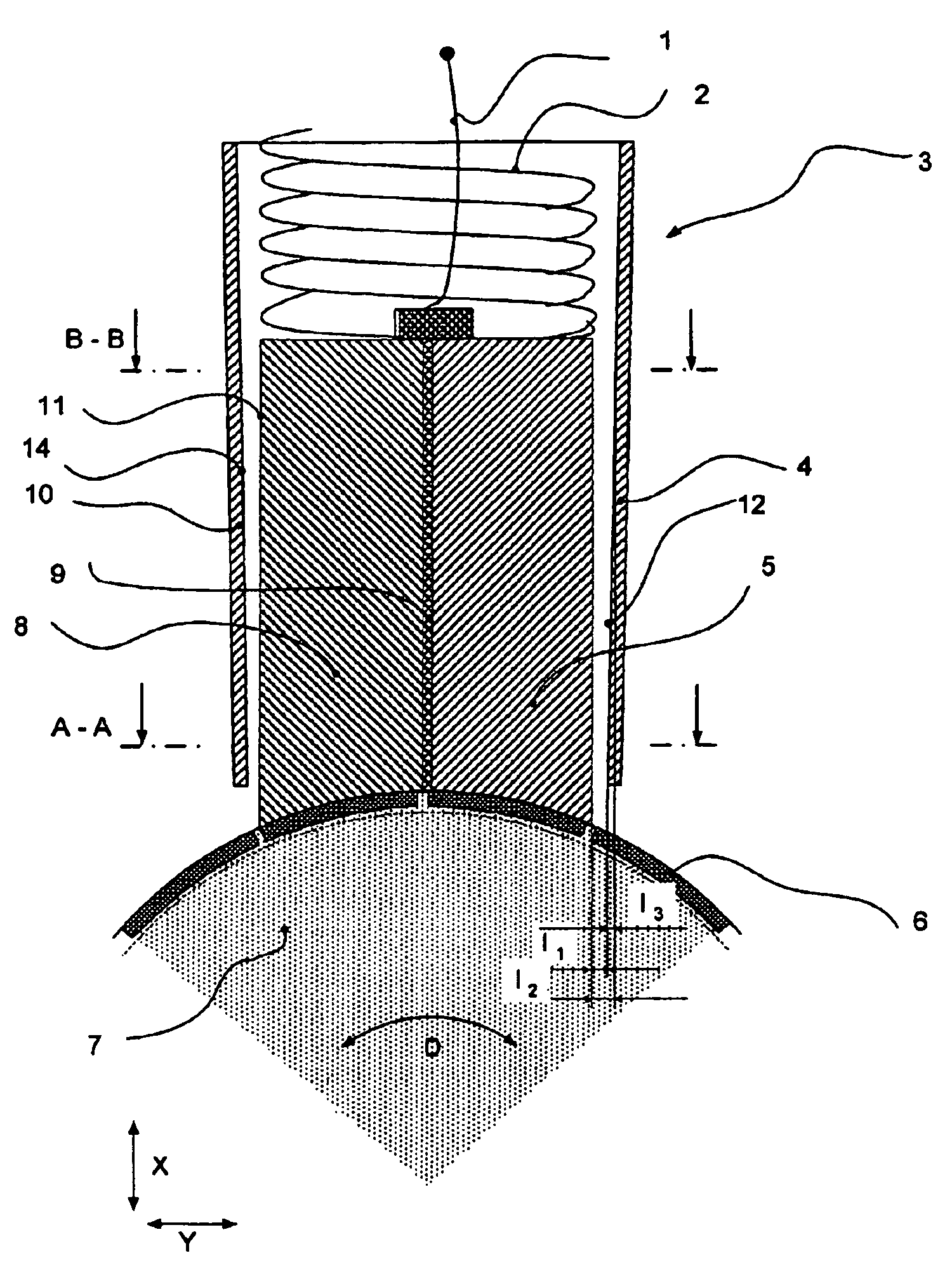
[0038]The description of the advantageous exemplary embodiment of the invention is made with reference to an application in an AC universal motor used to drive a rotatably mounted drum located in a laundry treatment appliance. However, the invention is not restricted to such a special design of a dynamo electric machine and the use of the machine in the laundry treatment device. Rather, the invention extends to current transfer units or brush bags and brushes which can be used in dynamo electric machines with a mechanical commutator.

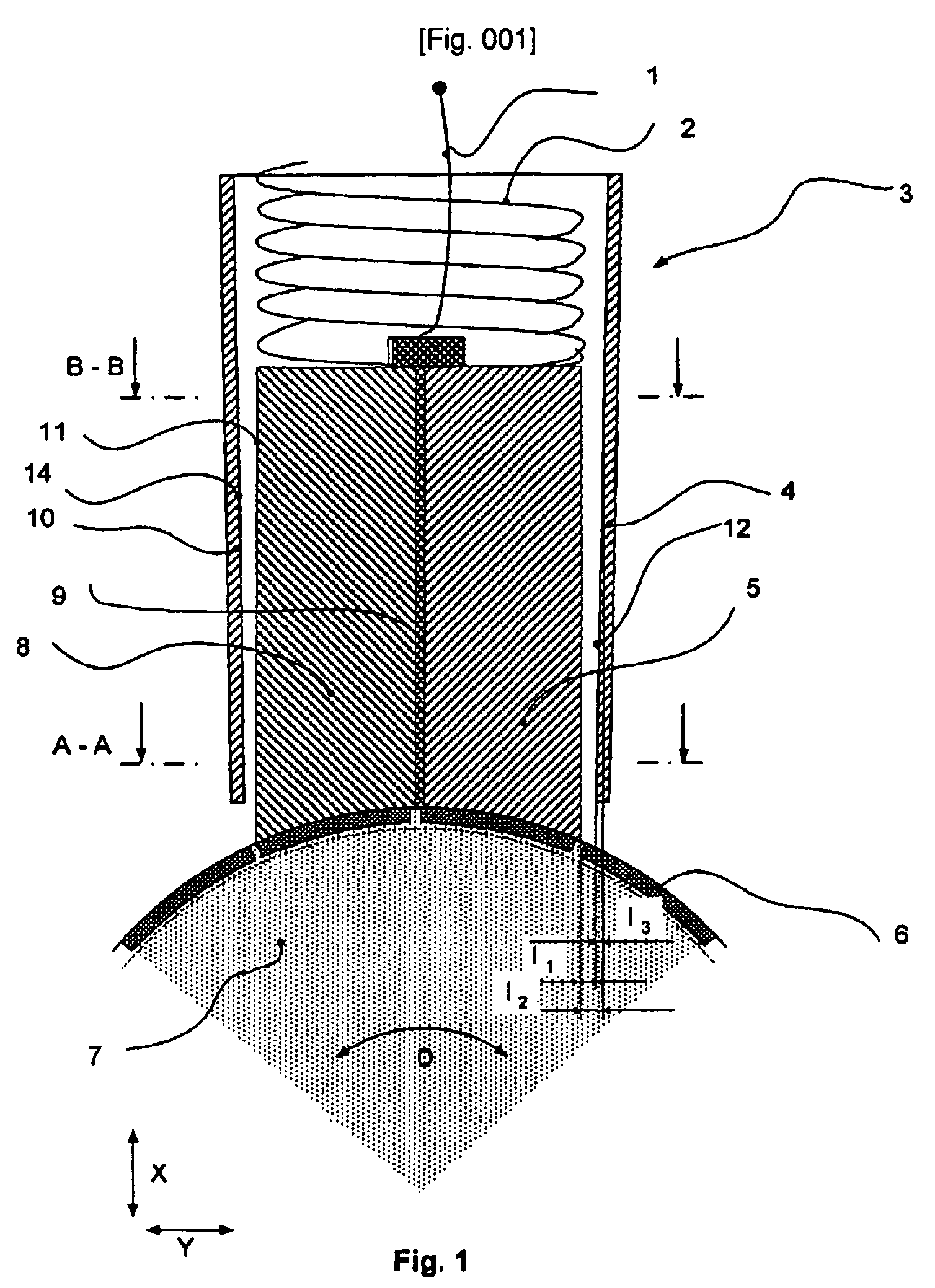
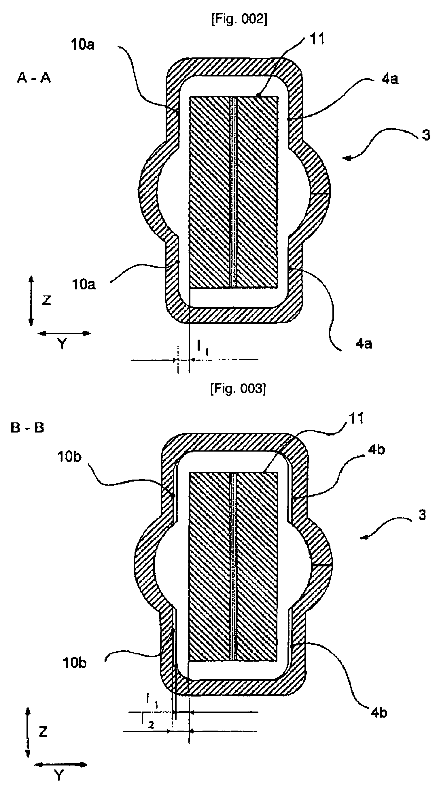
[0039]FIG. 1 shows a section through a current transfer unit and through a commutator 7 of an AC universal motor, not shown, which is hereinafter merely called the motor. The current transfer unit consists of a connecting lead 1, a multilayer carbon brush 11 which comprises two electrically conducting layers 5 and 8 and a high-resistance or electrically non-conducting layer 9 between these layers, a spring 2 and a fixed brush bag 3. The connecting lead 1...


PUM

PropertyMeasurementUnit
distanceaaaaaaaaaa
widthaaaaaaaaaa
widthaaaaaaaaaa

Abstract

A brush bag, a brush and a current transfer unit for a dynamo-electric machine comprising a commutator, in particular for an electromotor. The current transfer unit comprises at least the brush, which is embodied, in particular, as a multi-layer carbon brush, and a brush bag. The brush bag is configured in such a manner that the distance between the brush and the brush bag in a front guiding area is smaller than the distance in a rear guiding area. Beating of the brush on the brush bag is visibly reduced due to the configuration thereof and noise caused by the beat is avoided.

Description

BACKGROUND OF THE INVENTION[0001]The invention relates to a brush bag for a current transfer unit of a dynamo-electric machine, comprising a commutator, especially for an electric motor, wherein the brush bag, which is especially made of metal, has guiding areas for guiding a brush which is displaceable with respect to the longitudinal extension, which is especially embodied as a multi-layer carbon brush, and a spacing is provided between the guiding areas and the brush transverse to the longitudinal extension of the brush. In addition, the invention relates to a brush for the brush bag, a current transfer unit for a dynamo-electric machine comprising the brush bag and / or the brush or a dynamo-electric machine comprising such a current transfer unit and a method for producing the brush bag.[0002]The current transfer unit is a so-called sliding contact system which ensures the electrical connection between a power supply or external connections of the dynamo-electric machine and wind...

Claims


Application Information

Patent Timeline
Patent Type & Authority Patents(United States)
IPC IPC(8): H02K13/00H01R39/26H01R39/40
CPCH01R39/26H01R39/40Y10T29/49011H01R39/00
Inventor SCHACH, RAINERSKRIPPEK, JOERG
Owner BSH BOSCH & SIEMENS HAUSGERAETE GMBH
Why Eureka
Try Eureka