
Vibration gyro

a vibration gyro and kinetic balance technology, applied in the field of vibration gyro, can solve the problem of high s/n and achieve the effect of preventing vibration from leaking into the base section, reducing the total length of the resonator, and improving the kinetic balance of the detection leg and the drive leg

Inactive Publication Date: 2010-03-09
CITIZEN WATCH CO LTD
View PDF13 Cites 14 Cited by
  • Summary
  • Abstract
  • Description
  • Claims
  • Application Information

AI Technical Summary

Benefits of technology

The present invention provides a vibration gyro with a resonator that has improved kinetic balance and vibration detection. The resonator includes three legs with equal thickness joined to a base section. The detection leg has a wider distal end section and a smaller width in the portion other than the distal end section. The resonator also includes a support section that attaches the base section and the three legs to a package, which prevents vibration leakage and increases the Q factor. The base section and support section are integrally formed to further improve the Q factor. These improvements lead to a vibration gyro with higher signal-to-noise ratios and better performance.

Problems solved by technology

The problem is that a higher S / N is necessary to obtain a high accuracy.

Method used


Image

  • Vibration gyro
  • Vibration gyro
  • Vibration gyro

Examples


first embodiment

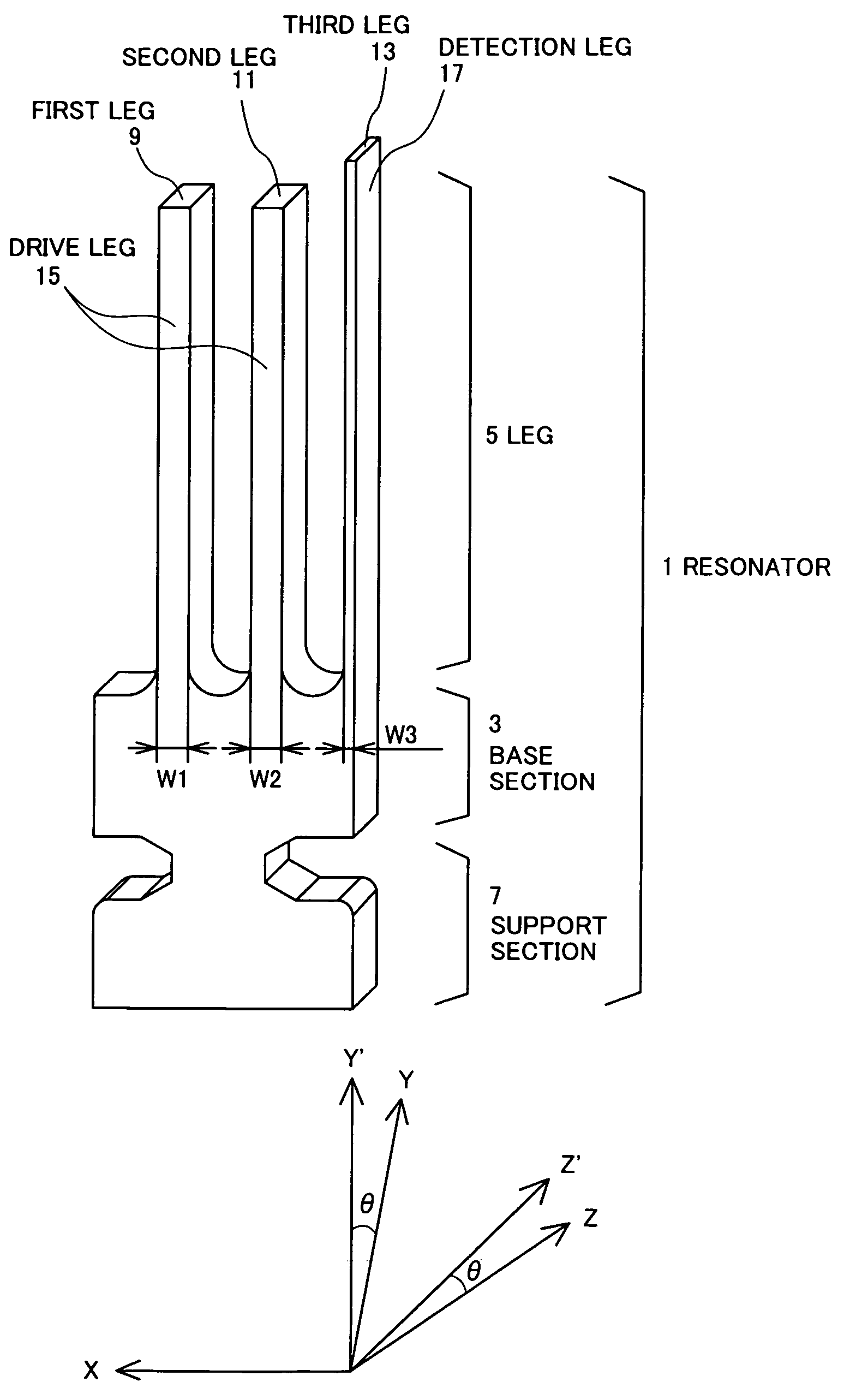
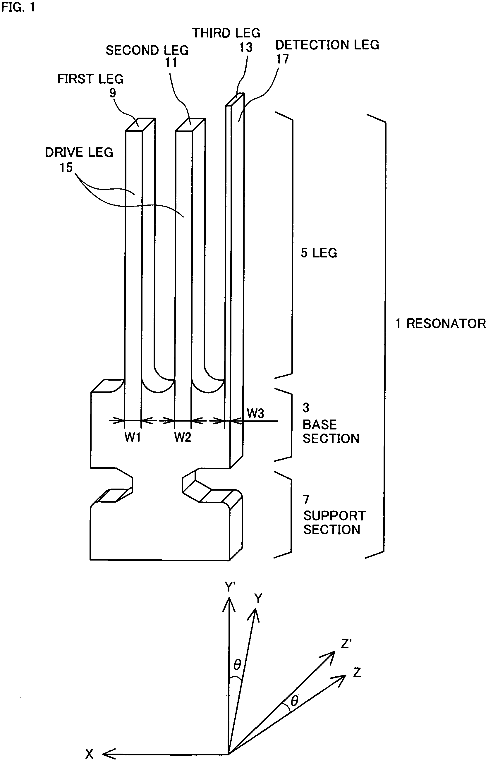
[0060]The vibration gyro of the first embodiment of the present invention will be described below with reference to the appended drawings. The vibration gyro of the present embodiment uses a resonator 1 shown in FIG. 1.

[0061]The resonator 1 shown in FIG. 1 is made from quartz and comprises a base section 3, three legs 5 extending from the base section 3, and a support section 7 extending from the base section 3 in the direction opposite that of the legs 5. The quartz is an anisotropic piezoelectric single crystal belonging to a trigonal crystal system and has as crystal axes an optical axis (Z axis), an electric axis (X axis), and a mechanical axis (Y axis) perpendicular to the optical axis and electric axis.

[0062]Where the direction parallel to the legs is taken as the X axis, and the directions obtained by rotating through an angle θ from the directions of Y axis and Z axis about the X axis as the rotation axis are taken as an Y′ axis and a Z′ axis, respectively, then the extensio...

second embodiment

[0096]The vibration gyro of the second embodiment of the present invention will be described below with reference to the appended drawings. The vibration gyro of the present embodiment uses a resonator 1 shown in FIG. 12. The resonator 1 shown in FIG. 12 is made from quartz and comprises, similarly to the resonator of the first embodiment, a base section 3, three legs 5 extending from the base section 3, and a support section 7 extending from the base section 3 in the direction opposite that of the legs 5. The quartz is an anisotropic piezoelectric single crystal belonging to a trigonal crystal system and has as crystal axis an optical axis (Z axis), an electric axis (X axis), and a mechanical axis (Y axis) perpendicular to the optical axis and electric axis.

[0097]Where the direction parallel to the legs is taken as the X axis, and the directions obtained by rotating through an angle θ from the directions of Y axis and Z axis about the X axis as the rotation axis are taken as an Y′ ...


PUM


Abstract

A vibration gyro having a high accuracy, no vibration leak, and high S / N.The width of a detection leg of a resonator used in the vibration gyro is less than ⅗ of the width of drive legs. The length of the detection leg is larger than the length of the drive legs. As a result, the distance between the detection electrodes is decreased by comparison with the conventional vibration gyro and, therefore, the detection signal is increased and S / N is raised. Furthermore, increasing the leg length brings the natural vibration frequency of out-of-plane vibration of the drive legs close to the natural vibration frequency of the detection leg, providing good coupling and reducing vibration leak to the support section. As a result, Q is increased and S / N is accordingly further increased.

Description

BACKGROUND OF THE INVENTION[0001]1. Field of the Invention[0002]The present invention relates to a vibration gyro used for detecting an angular velocity.[0003]2. Description of The Related Art[0004]Vibration gyros have been used for detecting shaking, for example, in shaking prevention mechanisms of household video cameras or position detection mechanisms of car navigation systems, or for detecting a rotation speed of a vehicle body.[0005]According to laws of physics, when viewed from a coordination system rotating at an angular velocity of Ω, a Coriolis force Fc proportional to the relative velocity V of a moving physical body acts upon the physical body in the direction perpendicular to that of the velocity. The magnitude and direction of this force are represented by the following equation:Fc=2 mV×Ω  (1)Here, m is the mass of the physical body upon which the Coriolis force acts.[0006]A vibration gyro is an angular velocity sensor in which a resonator is caused to vibrate and a ro...

Claims


Application Information

Patent Timeline
Patent Type & Authority Patents(United States)
IPC IPC(8): G01P9/04H01L41/08G01C19/56G01C19/5621H01L41/18H01L41/187
CPCG01C19/5607G01C19/5614
Inventor YAMAMOTO, IZUMI
Owner CITIZEN WATCH CO LTD
Learn More