
Folding device and printing system

a printing system and folding device technology, applied in the field of folding devices, can solve the problems of increasing the rigidity of paper, and affecting the folding effect of continuous paper, so as to facilitate maintenance, prevent the occurrence of folding defects, and facilitate continuous paper feed.

Inactive Publication Date: 2010-03-09
TORAY ENG CO LTD
View PDF18 Cites 7 Cited by
  • Summary
  • Abstract
  • Description
  • Claims
  • Application Information

AI Technical Summary

Benefits of technology

The present invention provides a folding device for continuous paper that can prevent folding defects, such as jams, and allow for stable feeding of continuous paper. The device includes a feeding member, a swinger fin, and a table for surmounting the continuous paper. The swinger fin swings in a zigzag pattern to feed the continuous paper into the device. The device is driven by a pulse motor and has a travel sensor to detect the condition of the continuous paper. The technical effects of the invention include improved maintenance, reduced folding defects, and stable paper feeding.

Problems solved by technology

As a result, occasionally, the paper is wrinkled or tensed, and the rigidity of the paper is increased by moisture loss of the paper.
Therefore, the folding of the continuous paper is sometimes difficult, so that the above-mentioned folding device is used in many cases.
The thin continuous paper expands and contracts to a large degree due to heating and pressing in the fixing process, and is then liable to be wrinkled and tensed.
For this reason, there occurs a folding jam more easily.
Accordingly, the toner-applied area and the non-applied area are different in heating degree, so that there occur imbalanced expansion and contraction, wrinkles and tension.
It is sometimes extremely difficult to get rid of them.
As a result, the feed of the continuous paper becomes unstable, which occasionally causes a folding jam.
With this structure, however, sometimes the continuous paper cannot be stably fed within the swinger fin at a correct rate.
Due to attraction of static electricity, friction resistance between the continuous paper and the inner surface of the swinger fin and the like is increased, which hampers the paper feedability.
This occasionally causes a folding jam in the swinger fin or on the table to be surmounted by the continuous paper that has been folded.
To add to such a complicated mechanism, if swing velocity and swing width are changed according to the top-and-bottom length of the paper and the paper feed rate, a more complicated adjustment mechanism is furthermore required.
This causes the disadvantage that the swinging motion of the swinger fin becomes unnatural, and that smooth paper folding is discouraged.
The oblique travel and the meandering travel often cause a folding jam.
Therefore, if the oblique or meandering travel occurs, the sensors often fail to immediately detect them.
The folding operation and the feed of the continuous paper are not stopped until a folding jam is detected, so that there have been the problem that a large quantity of folding-jammed continuous paper is produced.
This produces the problem that the oblique or meandering travel is liable to occur, incurring more folding-jammed continuous paper.
In case that the printer or printing device has the fixing process performed by the flash-fusing method, there also is the problem that, due to the imbalanced expansion and contraction of the paper, the oblique or meandering travel more easily occurs, incurring more folding-jammed continuous paper.
The conventional folding device, however, has sometimes caused a folding defect attributable to a setting mistake or setting failure in respect of the distance between the paddle units, or the like.
The vane member has occasionally caused a paper jam or folding defect.
However, if the tip end of the continuous paper is set to a wrong position, it is impossible to start a smooth folding operation, which incurs a folding defect from time to time.
In some cases, however, the swinger fin, the paddle member, and the table cause a folding defect by being set to different positions from their respective standby positions.
In this process, the swinger fin gets in the way and hampers the removal of the continuous paper.
For this reason, there occasionally generates a feeding defect of the continuous paper and a folding defect attributable to the feeding defect.
As a result, the pins come off the sprocket holes to produce a feeding defect.
Particularly, thin continuous paper contracts to a great degree and causes a feeding defect more often.
In case that the printing device has the fixing process performed by a flash-fusing device, sometimes more feeding defects attributable to contraction of the continuous paper are produced.
In many cases, a folding defect has been caused at the start of a folding operation during the intermittent operation.
The folding defect at the start of the folding operation has occurred more often in case that the continuous paper is thin or that the printing device has the fixing process performed by the flash-fusing method.

Method used


Image

  • Folding device and printing system
  • Folding device and printing system
  • Folding device and printing system

Examples


Embodiment Construction

[0109]An embodiment of the present invention will be described below with reference to drawings.

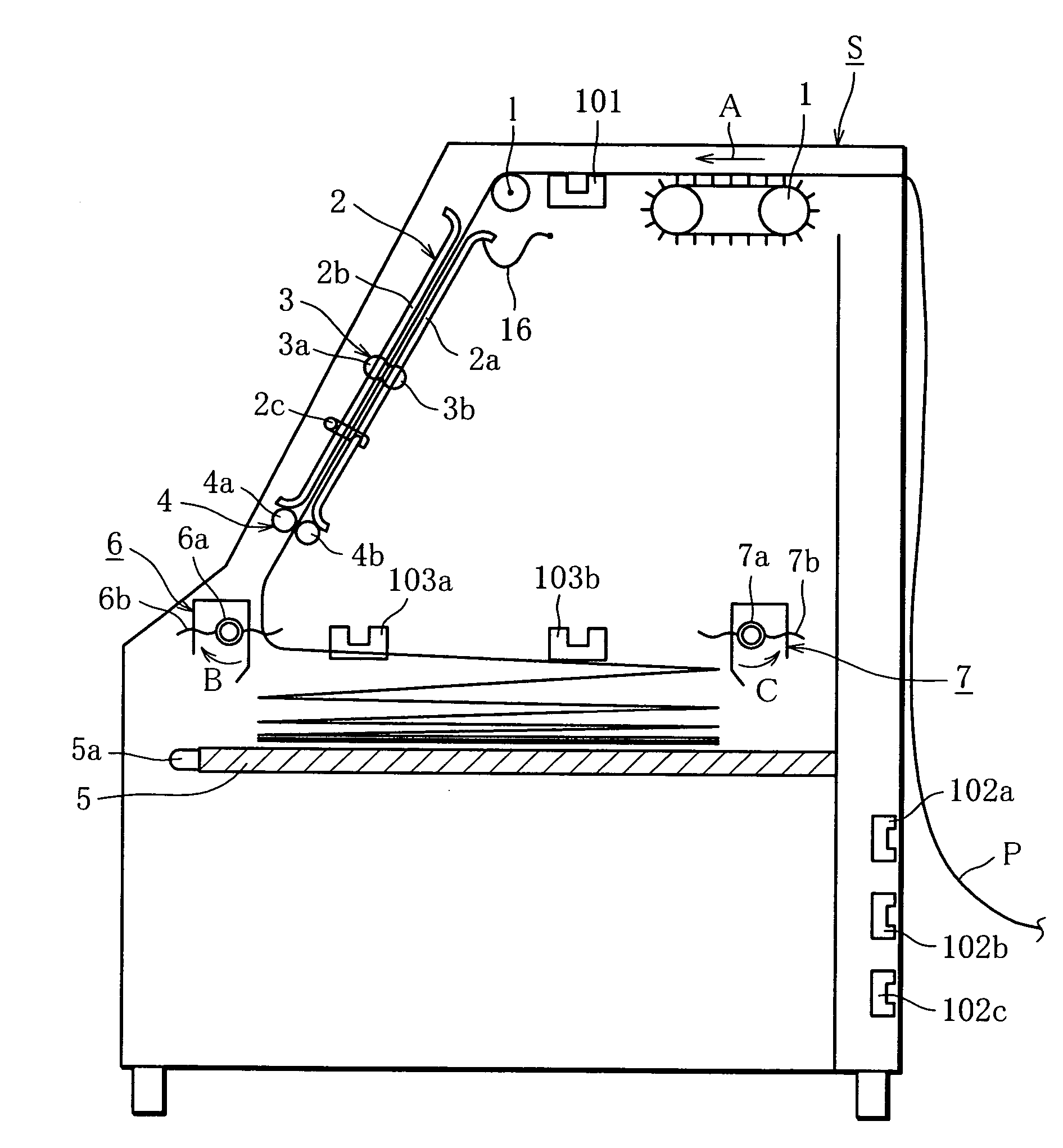
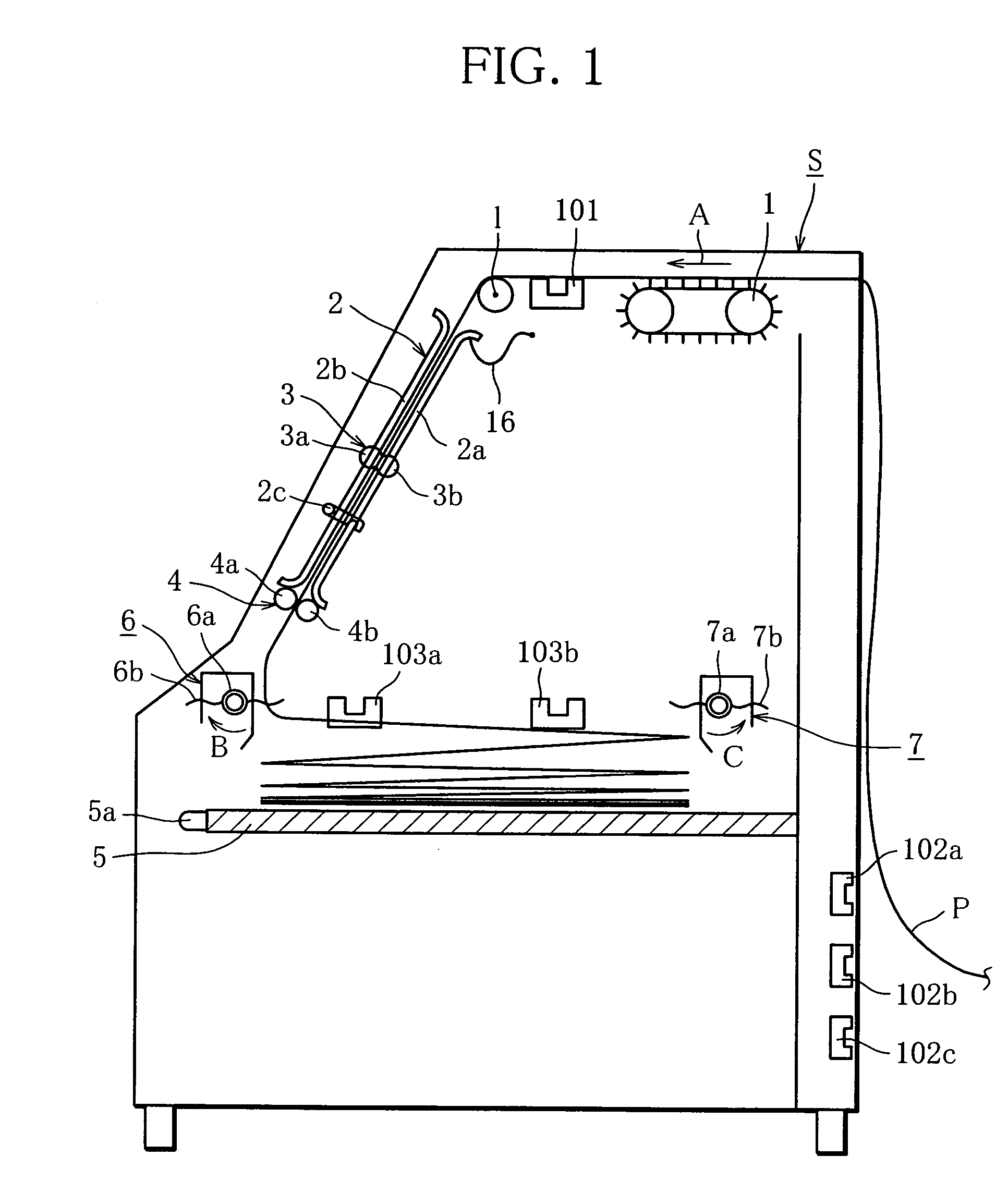
[0110]FIG. 1 is a sectional side view of a folding device according to one embodiment of the present invention.

[0111]In FIG. 1, reference character “P” represents continuous paper to be folded, and “S” denotes the folding device. “1” denotes a pin tractor serving as a feeding member for feeding the continuous paper P. The pin tractor feeds the continuous paper P at constant rate in a direction of arrow A in FIG. 1.

[0112]FIG. 8 shows details of a periphery of the pin tractor. The pin tractor is made up of a pair of pin-tractor units 1a and 1b located in both width-directional edges of the paper. Pins 25 disposed on pin belts 24 of the pin tractors 1a and 1b, which is arranged in both the edges of the continuous paper P, are fit into sprocket holes 26 of both edge portions of the continuous paper P, to thereby set the continuous paper P onto the pin tractors 1a and 1b. The pin tractors 1a a...


PUM

PropertyMeasurementUnit
lengthaaaaaaaaaa
lengthaaaaaaaaaa
distanceaaaaaaaaaa

Abstract

A folding device for folding continuous paper, which is previously provided with fold lines at given intervals, along the fold lines in a zigzag pattern. The folding device comprises a feeding member of the continuous paper, a swinger fin that swings using its one end as a fulcrum like a pendulum in synchronization with the fold lines while feeding the continuous paper into its inside, and a table to be surmounted by the continuous paper that has been folded. The swinger fin includes a feed roller pair for feeding the continuous paper while sandwiching the paper therebetween, and at least a pair of guide plates facing each other with a given gap therebetween, in which the continuous paper is fed through the gap. One of the feed rollers constructing the feed roller pair and one of the guide plates, which are located on one side of the continuous paper, can be integrally opened or detached from the swinger fin.

Description

TECHNICAL FIELD[0001]The present invention relates to a folding device for folding continuous paper along fold lines of the paper in a zigzag pattern.BACKGROUND ART[0002]Commonly in a printing device, such as a printer and a printing machine, which prints on continuous paper previously provided with fold lines at given intervals as viewed in a paper-feeding direction, a folding device is used to refold the printed continuous paper. In this specification, each of the given intervals is called a top-and-bottom length.[0003]Especially in case that the printing device is an electrophotographic printer, the paper is often heated and pressed in a fixing process. The heating and the pressing make the continuous paper expand and contract. As a result, occasionally, the paper is wrinkled or tensed, and the rigidity of the paper is increased by moisture loss of the paper. Therefore, the folding of the continuous paper is sometimes difficult, so that the above-mentioned folding device is used ...

Claims


Application Information

Patent Timeline
Patent Type & Authority Patents(United States)
IPC IPC(8): B41L1/32B65H23/04B65H45/101B65H45/107B65H45/109
CPCB65H23/042B65H45/1015B65H45/107B65H45/109
Inventor MIZUNO, YASUHISAKANAMORI, HAJIMEMURAKAMI, RIKI
Owner TORAY ENG CO LTD
Learn More