Apparatus and method for driving backlight unit

a backlight unit and apparatus technology, applied in the direction of electric variable regulation, process and machine control, instruments, etc., can solve the problems of increasing cost, complicated drive circuit by addressing, and uneven luminance values of leds individually, and achieve the effect of extremely uniform control

Active Publication Date: 2010-03-09
SATURN LICENSING LLC
View PDF20 Cites 30 Cited by
  • Summary
  • Abstract
  • Description
  • Claims
  • Application Information

AI Technical Summary

Benefits of technology

[0020]In the drive apparatus and the drive method according to the present invention, in a system of driving LED elements used as the liquid crystal backlight, detection result of the photo-sensor relating to an arbitrary color is caused to be reference to monitor other colors to perform feedback of relative percentage (ratio), and to change the ratio subject to feedback on the basis of detection results of the temperature sensors, thus making it possible to perform extremely uniform control.

Problems solved by technology

However, when drive circuits are assembled with respect to individual LEDs, in the case where the number of LEDs is large, the circuit configuration becomes complicated so that cost is increased.
Meanwhile, LEDs individually have unevennesses of luminance values.
Namely, in the case where the number of LED elements is large, drive circuit by addressing would become complicated.
In addition, in actual circuits having large powers of respective LED elements and used in LED drive operation for illumination purpose, since LSI, etc. for large power drive is not yet prepared, the cost is increased in the matrix type drive system so that it is economically disadvantageous.
Meanwhile, in the configuration as described above, since temperature dependencies of light emission outputs of respective color systems are also different and temperature characteristics are not uniform, it is necessary to perform adjustment of pulse width every colors by drive circuits dedicated for respective colors.
Further, since colors of rays of light emitted from the LED elements have uneven accuracies every respective colors by differences of resolutions of respective color systems, adjustment of balance of RGB and / or adjustment of white light become difficult.
Accordingly, in the case where there is only employed a method of detecting light quantities of LED elements of respective colors by the photo-sensors, it is impossible to correct change of color tone.

Method used


Image

  • Apparatus and method for driving backlight unit
  • Apparatus and method for driving backlight unit
  • Apparatus and method for driving backlight unit

Examples


Embodiment Construction

[0042]Embodiments of the present invention will be explained in detail with reference to the attached drawings.

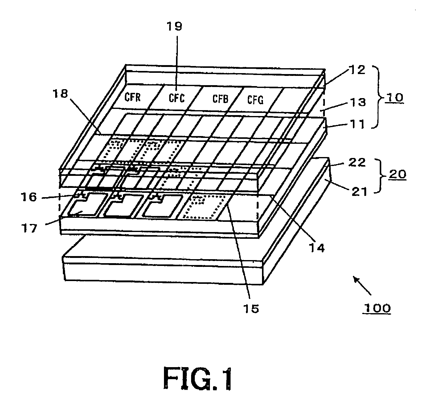
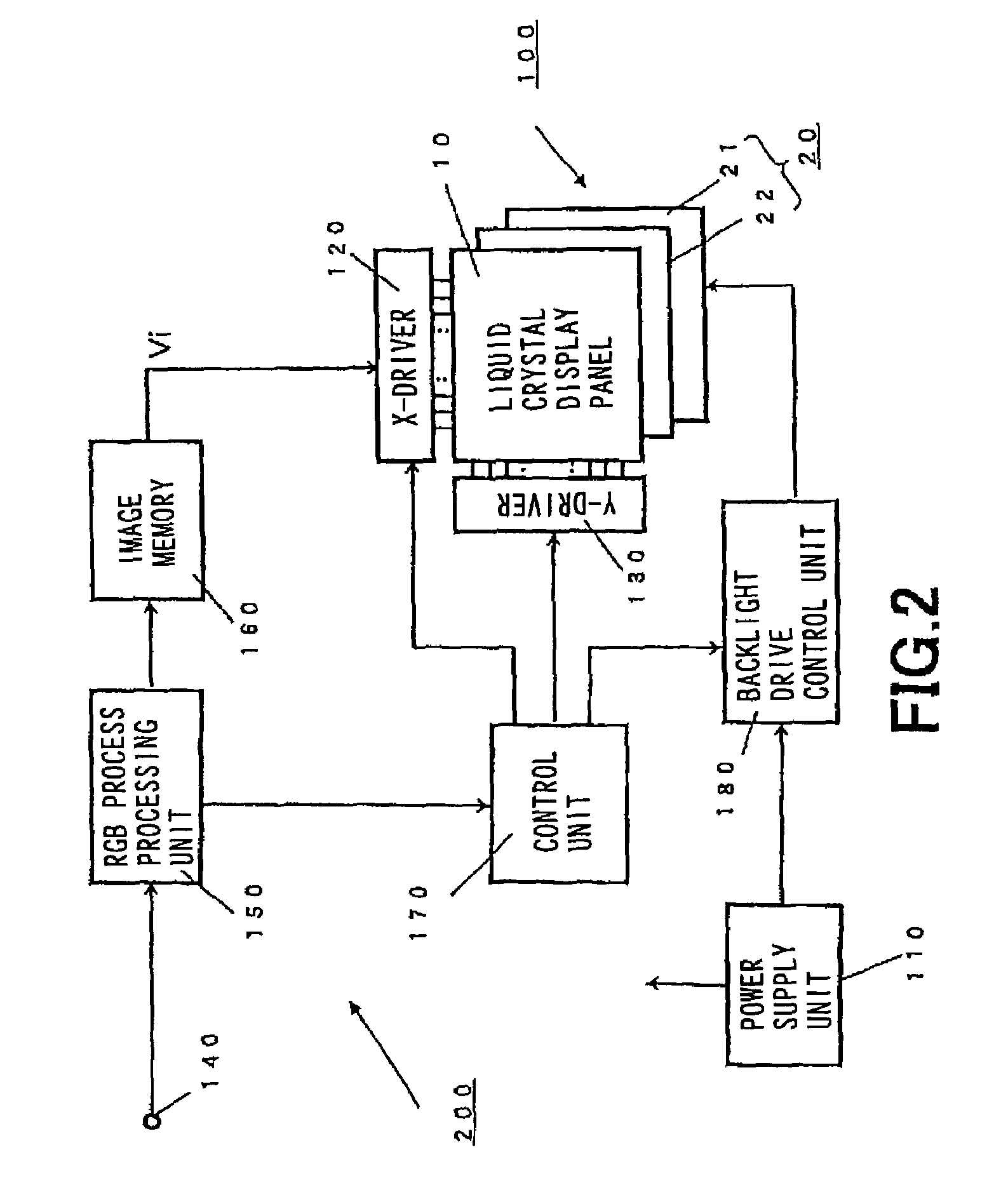
[0043]The present invention is applied to, e.g., a color liquid crystal display apparatus 100 of the backlight system of the configuration as shown in FIG. 1.

[0044]The color liquid crystal apparatus 100 shown in FIG. 1 comprises the transmission type color liquid crystal display panel 10, and a backlight unit 20 provided at the rear face side of the color liquid crystal display panel 10.

[0045]The transmission type color liquid crystal display panel 10 has the configuration in which a TFT base (substrate) 11 and an opposite electrode base (substrate) 12 are arranged opposite to each other, and a liquid crystal layer 13 in which, e.g., twisted nematic (TN) liquid crystal is filled is provided at the spacing therebetween. On the TFT base 11, there are formed signal lines 14 and scanning lines 15 which are arranged in a matrix form, and thin film transistors 16 as switching ele...


PUM


Abstract

The present invention is directed to a drive apparatus for a backlight unit (20) in which plural LED (Light Emitting Diode) elements are cascade-connected every three primary colors, which comprises a signal generating unit (44) for generating a signal having an arbitrary amplitude, an adjustment unit (50) for adjusting light emission quantities of groups of LED elements (30) on the basis of the signal which has been generated by the signal generating unit (44), a voltage applying unit (41) for applying a predetermined voltage every the groups of LED elements (30), light emission quantity detecting units (33) for detecting quantities of rays of light which have been emitted from the groups of LED elements (30), calorific value detecting units (32) for detecting calorific values emitted from the groups of LED elements in accordance with the voltage which has been applied to the voltage applying unit (41), and a control unit (50) for controlling the signal generating unit (44) on the basis of light emission quantities which have been detected by the light emission quantity detecting units (33) and calorific values which have been detected by the calorific value detecting units (32).

Description

TECHNICAL FIELD[0001]The present invention relates to a drive apparatus and a drive method which are adapted for performing drive control of a backlight unit comprised of groups of LED elements.[0002]This Application claims priority of Japanese Patent Application No. 2004-205146, filed on Jul. 12, 2004, and Japanese Patent Application No. 2004-336373, filed on Nov. 19, 2004, the entireties of which are incorporated by reference herein.BACKGROUND ART[0003]In display devices using LED (Light Emitting Diode) elements as display pixels, in order to perform matrix drive operation of the LED elements, X-Y addressing drive circuits are required for respective pixels. The display device serves to perform selection (addressing) of a LED element located at the position of pixel desired to be emitted (lighted) by addressing drive circuit to modulate lighting time by, e.g., PWM (Pulse Width Modulation) drive system to execute luminance adjustment to obtain display picture having a predetermined...

Claims


Application Information

Patent Timeline
Patent Type & Authority Patents(United States)
IPC IPC(8): H05B37/02H05B44/00H01L33/00
CPCG09G3/3413G09G3/342H05B33/0818H05B33/0857H05B33/0872H05B33/0815G09G2320/041G09G2360/145G09G2320/064G09G2320/0633H05B45/28H05B45/20H05B45/37H05B45/3725
Inventor FURUKAWA, NORIMASAICHIKAWA, HIROAKIKIKUCHI, KENICHI
Owner SATURN LICENSING LLC
Why Eureka
Try Eureka