Acoustic galvanic isolator incorporating single decoupled stacked bulk acoustic resonator

a technology of acoustic resonators and isolators, which is applied in piezoelectric/electrostrictive device details, impedence networks, device details, etc., can solve the problems of inconvenient fabrication, inconvenient use, and inability to provide an absolute break in the conduction path of capacitors, etc., and achieves the effect of being inexpensive to fabrica

Inactive Publication Date: 2010-03-09
AVAGO TECH INT SALES PTE LTD
View PDF358 Cites 9 Cited by
  • Summary
  • Abstract
  • Description
  • Claims
  • Application Information

AI Technical Summary

Problems solved by technology

Inexpensive opto-isolators are typically limited to data rates of about 10 Mb / s by device capacitance, and from power limitations of the optical devices.
Such conflicting requirements are often difficult to reconcile.
Using capacitors does not provide an absolute break in the conduction path because the information signal is transmitted electrically throughout.

Method used


Image

  • Acoustic galvanic isolator incorporating single decoupled stacked bulk acoustic resonator
  • Acoustic galvanic isolator incorporating single decoupled stacked bulk acoustic resonator
  • Acoustic galvanic isolator incorporating single decoupled stacked bulk acoustic resonator

Examples


first embodiment

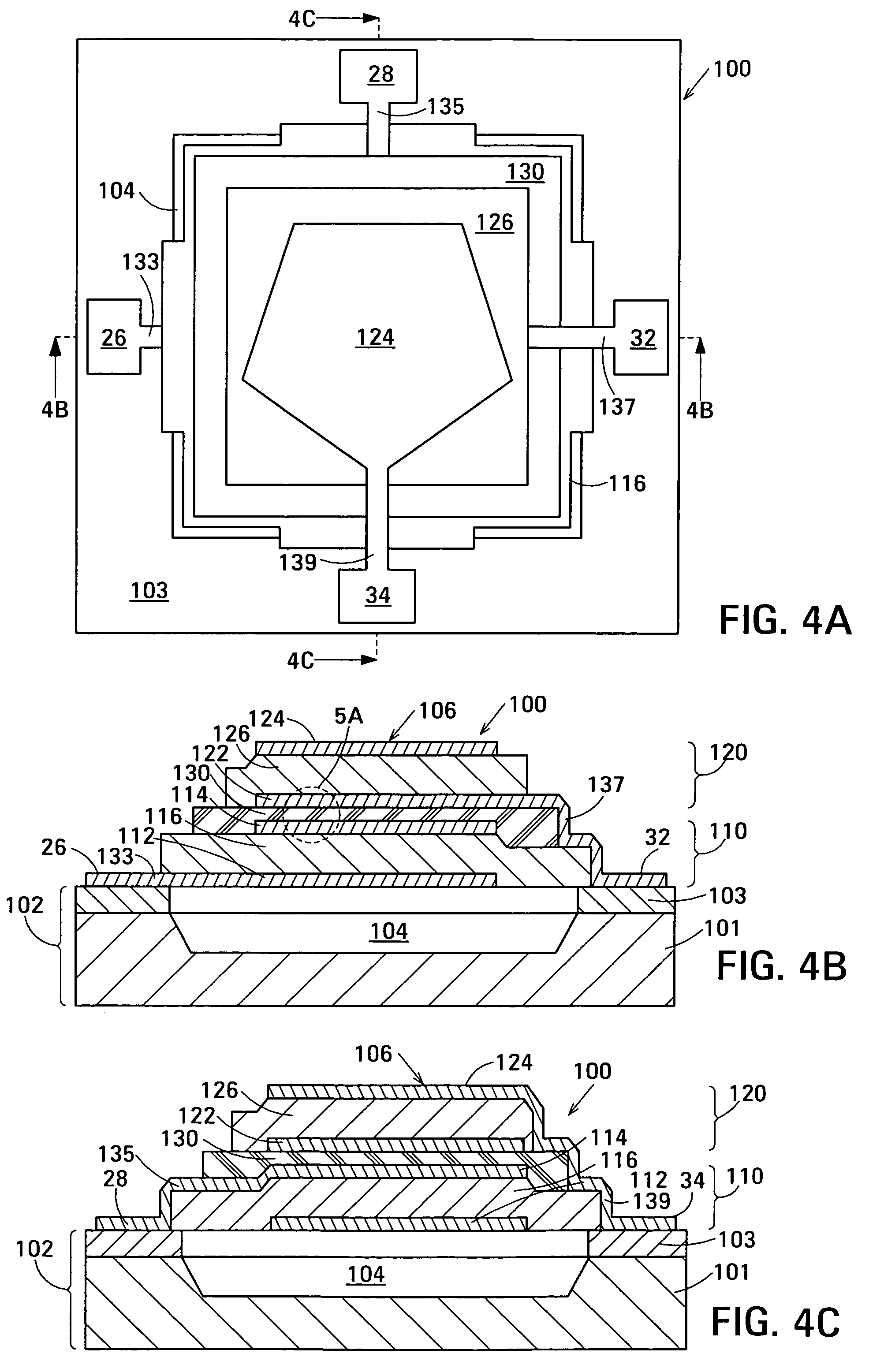
[0042]FIG. 5A is an enlarged view of the portion marked 5A in FIG. 4B showing electrically-insulating acoustic decoupler 130. In the embodiment shown in FIG. 5A, acoustic decoupler 130 is composed of an acoustic decoupling layer 131 of electrically-isolating acoustic decoupling material located between the electrodes 114 and 122 of FBARs 110 and 120, respectively. The acoustic decoupling material of acoustic decoupling layer 131 has an acoustic impedance intermediate between that of air and that of the materials of FBARs 110 and 120, and additionally has a high electrical resistivity and a high breakdown field.

[0043]The acoustic impedance of a material is the ratio of stress to particle velocity in the material and is measured in Rayleighs, abbreviated as rayl. The piezoelectric material of the piezoelectric elements 116 and 126 of FBARs 110 and 120, respectively is typically aluminum nitride (AIN) and the material of electrodes 112, 114, 122 and 124 is typically molybdenum (Mo). Th...

second embodiment

[0055]FIG. 5B is an enlarged view of the portion marked 5A in FIG. 4B showing electrically-insulating acoustic decoupler 130. In the embodiment shown in FIG. 5B, acoustic decoupler 130 is composed of an electrically-insulating acoustic Bragg structure 161. Electrically-insulating acoustic Bragg structure 161 comprises a low acoustic impedance Bragg element 163 located between high acoustic impedance Bragg elements 165 and 167. At least one of the Bragg elements 163, 165 and 167 of Bragg structure 161 comprises a layer of material having a high electrical resistivity, a low dielectric permittivity and a high breakdown field. Low acoustic impedance Bragg element 163 is a quarter-wave layer of a low acoustic impedance material whereas high acoustic impedance Bragg elements 165 and 167 are each a quarter-wave layer of high acoustic impedance material. The acoustic impedances of the materials of the Bragg elements are characterized as “low” and “high” with respect to one another and with...


PUM


Abstract

Embodiments of the acoustic galvanic isolator comprise a carrier signal source, a modulator connected to receive an information signal and the carrier signal, a demodulator, and an electrically-isolating acoustic coupler connected between the modulator and the demodulator. The acoustic coupler comprises no more than one decoupled stacked bulk acoustic resonator (DSBAR). An electrically-isolating acoustic coupler based on a single DSBAR is physically small and is inexpensive to fabricate yet is capable of passing information signals having data rates in excess of 100 Mbit / s and has a substantial breakdown voltage between its inputs and its outputs.

Description

RELATED APPLICATIONS[0001]This disclosure is related to the following simultaneously-filed disclosures: Acoustic Galvanic Isolator Incorporating Single Insulated Decoupled Stacked Bulk Acoustic Resonator With Acoustically-Resonant Electrical Insulator of John D. Larson III (U.S. patent application Ser. No. 11 / 253,508); Acoustic Galvanic Isolator Incorporating Film Acoustically-Coupled Transformer of John D. Larson III et al. (U.S. patent application Ser. No. 11 / 253,463); Acoustic Galvanic Isolator Incorporating Series-Connected Decoupled Stacked Bulk Acoustic Resonators of John D. Larson III et al. (U.S. patent application Ser. No. 11 / 253,444), and Acoustic Galvanic Isolator of John D. Larson III et al. (U.S. patent application Ser. No. 11 / 253,464), all of which are incorporated by reference.Background[0002]A galvanic isolator allows an information signal to pass from its input to its output but has no electrical conduction path between its input and its output. The lack of an elect...

Claims


Application Information

Patent Timeline
Patent Type & Authority Patents(United States)
IPC IPC(8): H03H9/54H01L41/04H01L41/083
CPCH03H9/584H03H9/587H03H9/02007H03H9/171H03H9/585
Inventor LARSON, III, JOHN D
Owner AVAGO TECH INT SALES PTE LTD
Why Eureka
Try Eureka