Compact optical system

a compact, optical technology, applied in the field of compact optical pupil forming systems, can solve the problem that the image device cannot be seen directly, and achieve the effect of reducing the number of elements required and reducing the volume required

Inactive Publication Date: 2010-03-09
NVIS
View PDF1 Cites 60 Cited by
  • Summary
  • Abstract
  • Description
  • Claims
  • Application Information

AI Technical Summary

Benefits of technology

[0018]This disclosure provides a novel method of making use of optical elements several times thus reducing the number of elements required for the task of forming a virtual image while at the same time reducing the volume required to complete the same task by doubling back through the space the elements occupy.

Problems solved by technology

The image device cannot be viewed directly, when placed before the observer's eye, due to the closeness of the device to the observer.
One of the challenges of building such a device is to make the optical elements compact while maintaining optical performance that will support the resolution of the imaging device.

Method used


Image

  • Compact optical system
  • Compact optical system
  • Compact optical system

Examples


Embodiment Construction

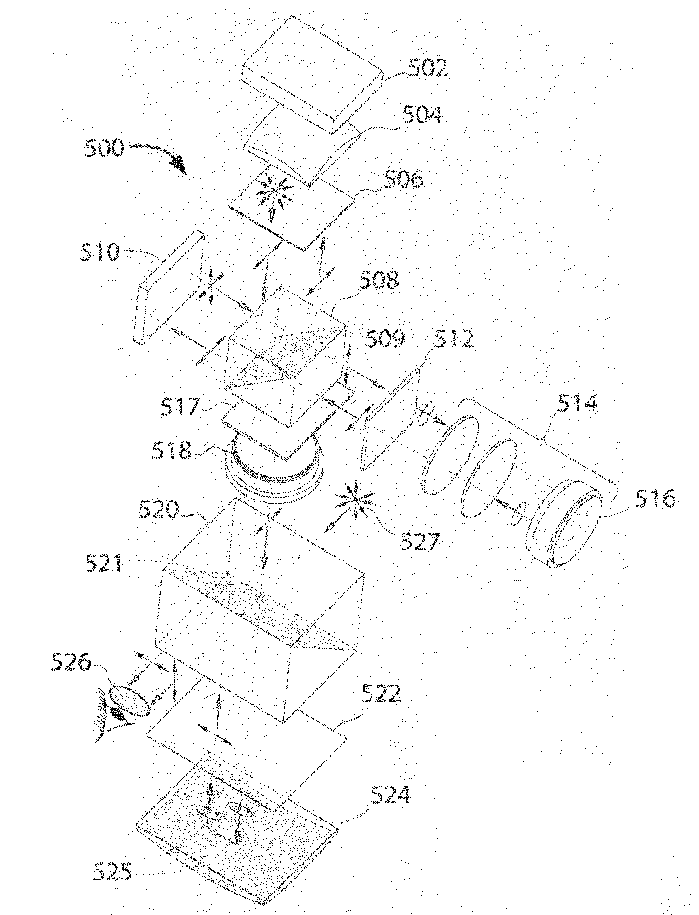
[0035]This disclosure relates to reducing the volume of an optical system by using optical components multiple times and using the compact optical system within a head-mounted display or other applications requiring a compact system with a long optical path. The schematic arrangement of an optical display constructed in accordance with the disclosure is illustrated as system 400 in FIG. 4.

[0036]The system forms a virtual image which is viewed from an external position. The system consists of 4 components or subsystems; 1) an illumination system; 2) a spatial light modulator (SLM); 3) a reflective relay system; 4) a viewing eyepiece. It is the purpose of the illumination system to illuminate the SLM. A real image is formed on the surface of the SLM. The relay lens system reforms an aerial image of the real image. The aerial image is then collimated by the eyepiece, becoming a virtual image. The virtual image is then observed by the eye of an observer.

[0037]Within such an optical syst...


PUM


Abstract

The invention relates to compact optical arrangement for a helmet mounted display. The arrangement is well suited to use with spatial light modulators which require front illumination such as LCoS modulators but can also be adapted to rear illuminated devices such as LCD's and to self luminous devices such as OLEDs. The device uses polarization and reflection to make dual use of both volumes and lenses.

Description

CROSS REFERENCE[0001]This application is related to provisional application Ser. No. 60 / 958,844 filed on Jul. 9, 2007 entitled “Design of a See-through Head-Mounted Display” and is hereby incorporated herein by reference.FIELD OF THE INVENTION[0002]The present invention relates to compound optical pupil forming systems. In particular, the invention relates to reducing the volume of an optical system by using a plurality of optical components multiple times.BACKGROUND OF THE INVENTION[0003]There is an increased interest in using miniature image devices carried on the head of an observer, head-mounted displays (HMD), to present information to the observer in a dynamic mode. The image device cannot be viewed directly, when placed before the observer's eye, due to the closeness of the device to the observer. Optical elements are used to create a virtual image of the image device at some distance so as to be comfortably viewed by the observer. One of the challenges of building such a dev...

Claims


Application Information

Patent Timeline
Patent Type & Authority Patents(United States)
IPC IPC(8): G02B27/14
CPCG02B27/0172G02B5/30G02B2027/0118
Inventor WEISSMAN, PAULBABLANI, MINOO
Owner NVIS
Why Eureka
Try Eureka