Multi-mode-multi-band wireless transceiver

a wireless transceiver and multi-mode technology, applied in the field of wireless transceivers, can solve the problems of burden on the transceiver, inconvenient use for users, and difficulty in relaxing so as to reduce the number and volume of elements, and the specification of the rf system can be weakened.

Inactive Publication Date: 2010-03-09
SAMSUNG ELECTRONICS CO LTD
View PDF12 Cites 28 Cited by
  • Summary
  • Abstract
  • Description
  • Claims
  • Application Information

AI Technical Summary

Benefits of technology

[0022]Accordingly, the present invention has been made to solve the above-mentioned problems occurring in the prior art, and an object of the present invention is to provide a multi-mode / multi-band wireless transceiver which includes a reduced number and volume of elements in a multi-mode or multi-band as well as in a single mode or a single band, and in which a specification of a RF system can be weakened.

Problems solved by technology

Therefore, when a user travels or makes a business trip to a region in which a communication service is different from that of his / her country, the use cannot use a mobile station of the region, which provides inconvenience for the user.
However, since the duplexer, or SAW filter, is a band pass filter which passes the service band, it is not helpful to improve an in-band blocking characteristic or to relieve Input 3rd Order Intercept Point (IIP3) and Input 2nd Order Intercept Point (IIP2) characteristics of a mixer which converts the received signal into a low band in the RF receiving portion.
Thus, it is difficult to relax a specification of the RF system.
Further, since a separate duplexer and the RF SAW filter are used in every service mode or in every frequency band, respectively, they are a burden to the transceiver in view of cost, volume and required mounting area.
However, since an inactive element, such as RF SAW filter, still does not have a small size, it is a burden to the transceiver.
In the case of supporting all the different service modes, such as FDD and TDD, since a duplexer for the FDD mode and a T / R switch for T / R switching must be separately used in the transceiver, they are a burden to the transceiver in view of cost, volume and required mounting area of the transceiver.

Method used


Image

  • Multi-mode-multi-band wireless transceiver
  • Multi-mode-multi-band wireless transceiver
  • Multi-mode-multi-band wireless transceiver

Examples


Embodiment Construction

[0031]Hereinafter, preferred embodiments of the present invention will be described in detail with reference to the accompanying drawings. In the following description of the present invention, a detailed description of known functions and configurations incorporated herein will be omitted to avoid making the subject matter of the present invention unclear.

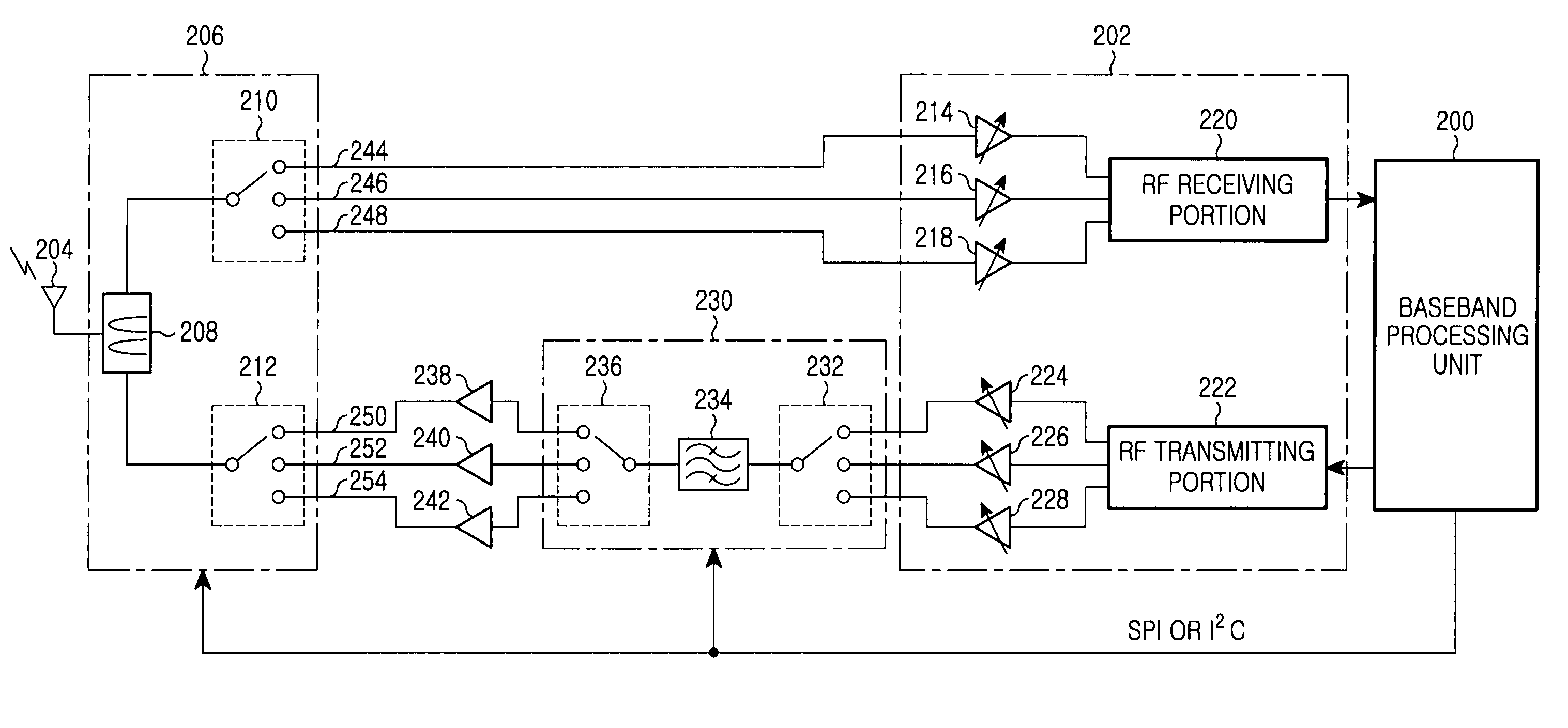
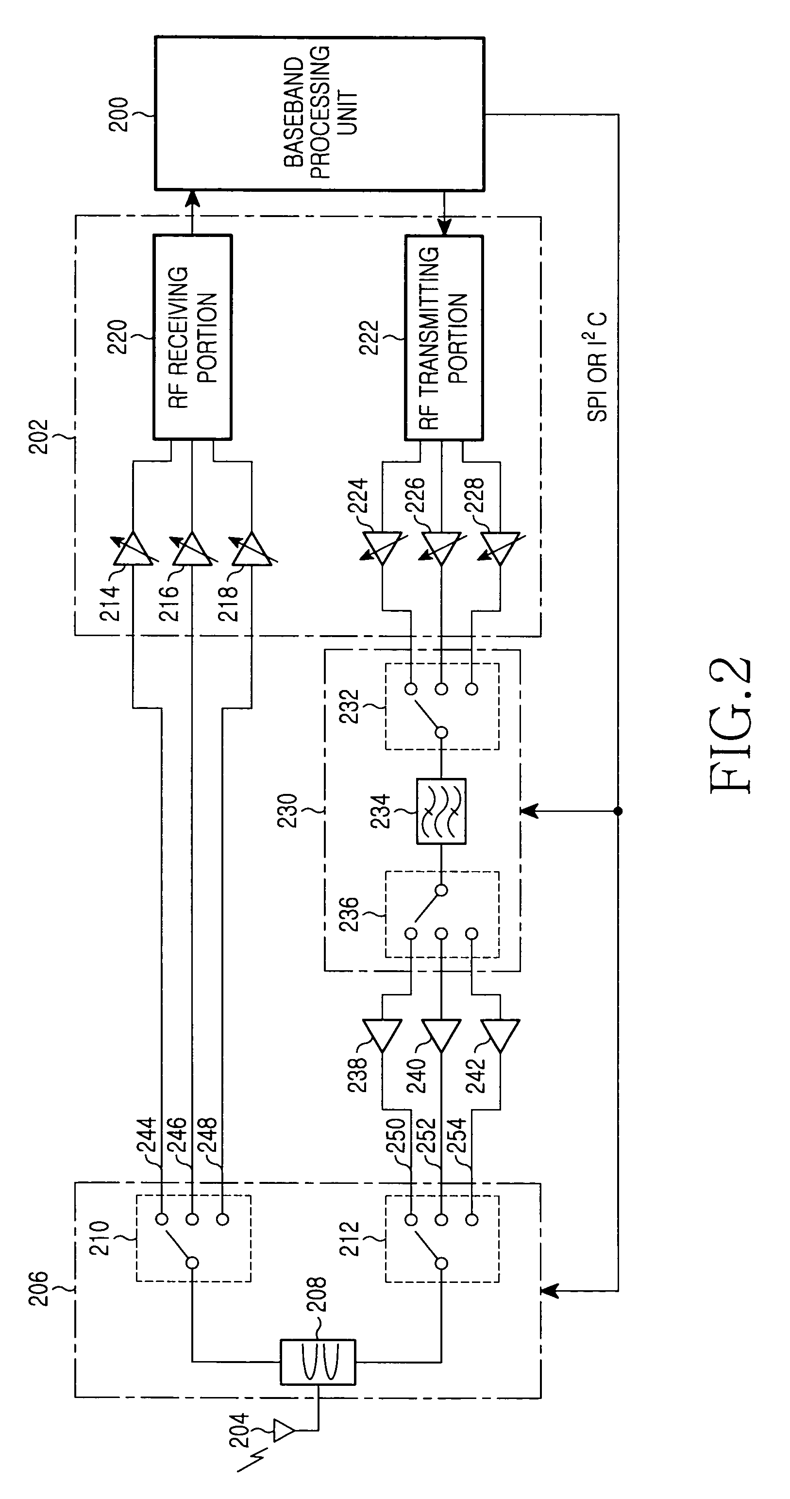
[0032]FIG. 2 is a block diagram illustrating a multi-mode / multi-band wireless transceiver according to an embodiment of the present invention: The multi-mode / multi-band wireless transceiver of FIG. 2 employs a tunable duplexer 208. The tunable duplexer 208 includes channel filter having a frequency response characteristics 304 and 306 as shown in FIG. 3, and is capable of varying transmission and reception channel filtering frequency, in a manner different from the duplexers 108, 110 and 112 of FIG. 1, which are band filters for filtering a service band.

[0033]FIG. 3 shows a comparison of frequency response characteristics of the t...


PUM


Abstract

Disclosed is a multi-mode / multi-band wireless transceiver. The multi-mode / multi-band wireless transceiver includes a tunable duplexer including transmission and reception channel filters of which transmission and reception channel filtering frequencies respectively are controlled by an external element; and a control portion for controlling the transmission and reception channel filtering frequencies to correspond to transmission and reception channels of a current service band. Thus, a use of a RF SAW filter is unnecessary, while it is possible to support the multi-mode / multi-band using a tunable duplexer. Therefore, the number of parts and volume of the transceiver can be reduced, and it is possible to weaken a specification of an RF system.

Description

PRIORITY[0001]This application claims priority to applications entitled “Multi-Mode / Multi-Band Wireless Transceiver” filed in the Korean Industrial Property Office on Aug. 17, 2005 and assigned Serial No. 2005-75301, and on Sep. 13, 2005 and assigned Serial No. 2005-85311 the contents of which are incorporated herein by reference.BACKGROUND OF THE INVENTION[0002]1. Field of the Invention[0003]The present invention relates to a wireless transceiver, and more particularly to a wireless transceiver supporting a multi-mode / multi-band.[0004]2. Description of the Related Art[0005]Generally, countries all over the world employ different communication schemes for mobile communication services and each of mobile communication schemes uses various frequency bands.[0006]The mobile communication schemes include, for example, a Code Division Multiple Access (CDMA) scheme, a Global System for Mobile (GSM) communication scheme, a General Packet Radio Service (GPRS) scheme, an Enhanced Data rates f...

Claims


Application Information

Patent Timeline
Patent Type & Authority Patents(United States)
IPC IPC(8): H04M1/00
CPCH04B1/006H04B1/0071H04B1/406H04B1/52
Inventor PARK, HYUNG-WEONSON, YOUNG-ILLEE, WOO-YONG
Owner SAMSUNG ELECTRONICS CO LTD
Why Eureka
Try Eureka