
Socks of multi-stage pile structure

a pile structure and multi-stage technology, applied in the field of socks, can solve the problems of not being able to provide cushion performance, being subjected to different degrees of shock, and feeling steamy, and achieve the effects of reducing shock, facilitating sweat absorption and transpiration, and reducing the feeling of swea

Inactive Publication Date: 2010-03-16
OKAMOTO INDS
View PDF21 Cites 53 Cited by
  • Summary
  • Abstract
  • Description
  • Claims
  • Application Information

AI Technical Summary

Benefits of technology

"The present invention provides a sock with a unique knitting structure in the ground-touching areas, such as the heel, sole, and toe, to improve its performance and comfort. The sock has terry stitches of different lengths and shapes to match the weight distribution and shock experienced by the wearer. The stitches are evenly distributed to prevent slipping and improve grip. The sock can also have different yarn materials for different purposes and to reduce the amount of yarn used. Additionally, the sock can be tailored for different activities and can be made with different thicknesses and shapes to provide better fit and comfort."

Problems solved by technology

Because of this structure, the sole portion of the sock tends to be thick across its entire area, preventing the transpiration of sweat and in-shoe humidity, and causing a steamy feel.
Moreover, because the sole portion is thick across its entire area, the wearer has to choose a shoe of a larger size than his / her actual foot size.
However, even within the same section, e.g., the sole portion, different areas are of different shapes and are subjected to different degrees of shock when walking or running.
The sock disclosed in Document 2 above cannot provide a cushion performance that complies with the ground-touching pressure distribution on the sole portion.
Because the terry stitches have the same length within the same section, there is not enough space between the sole of the foot and the sock that eliminate the steamy feel.

Method used


Image

  • Socks of multi-stage pile structure
  • Socks of multi-stage pile structure
  • Socks of multi-stage pile structure

Examples


Embodiment Construction

[0036]The best mode of carrying out the present invention will now be explained by reference to an example.

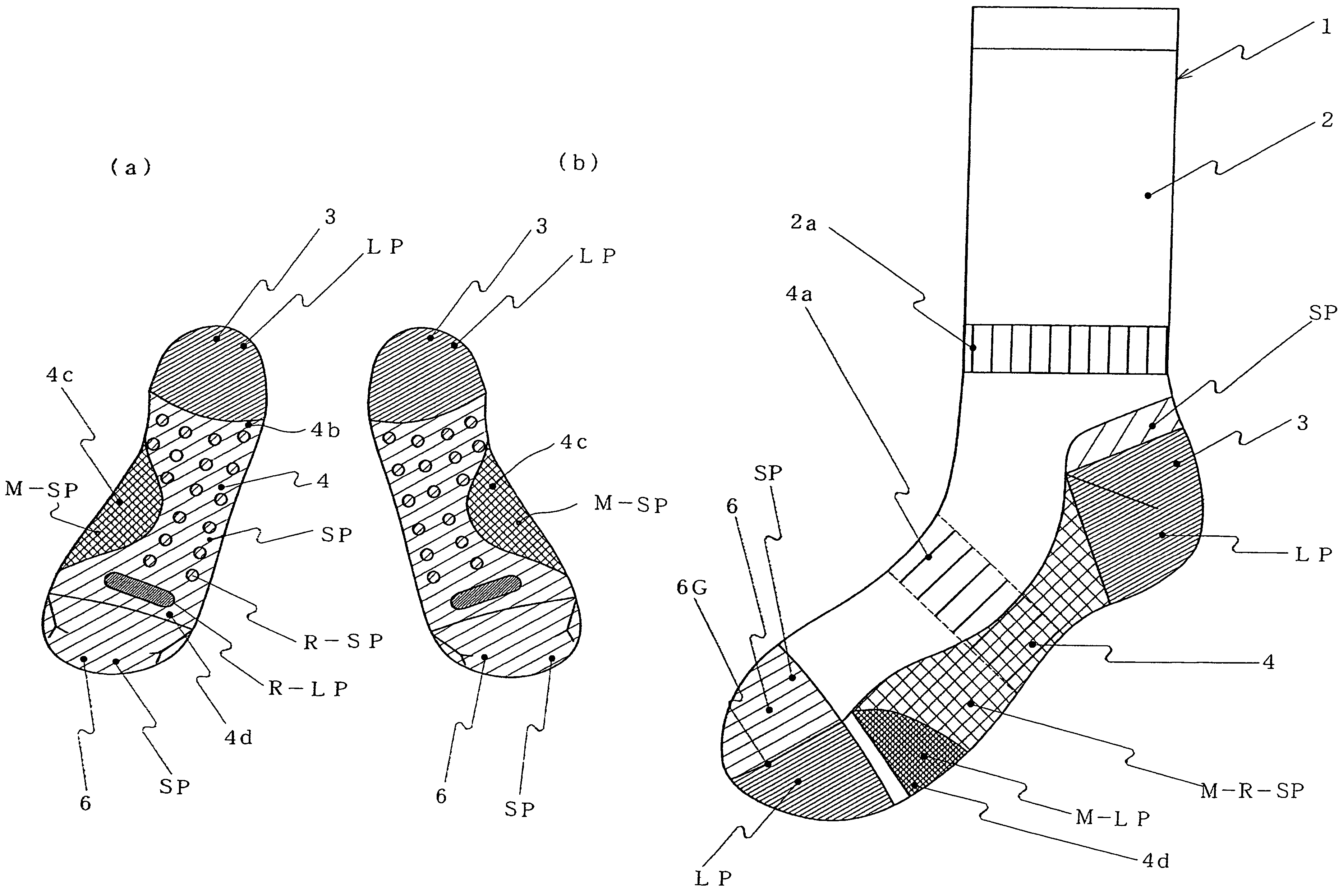
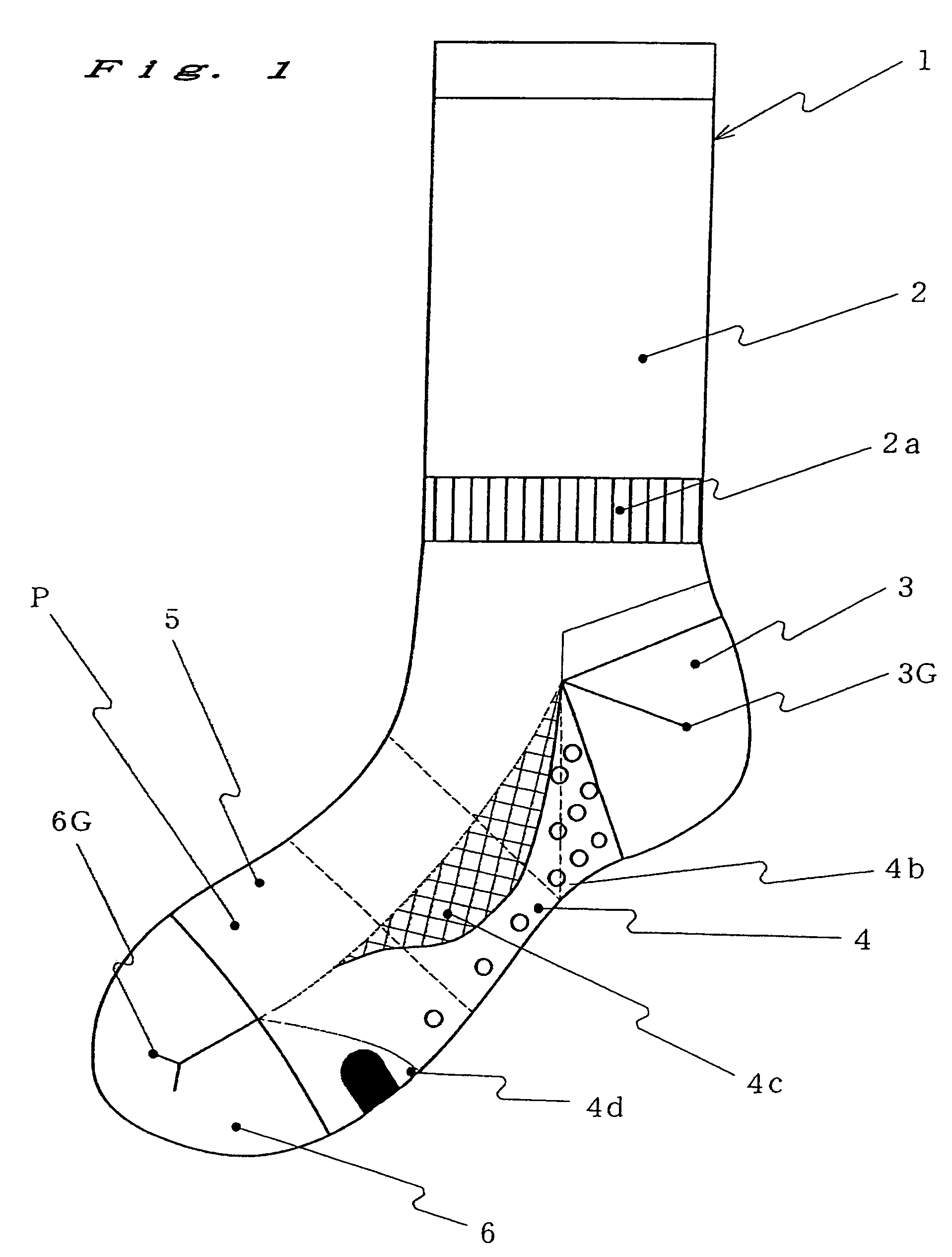
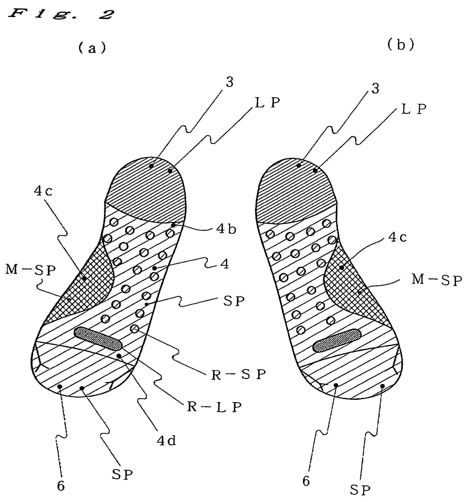
[0037]Let us assume making a sock using a plain-stitch fabric having a thickness of 1. A long-terry stitch LP portion having a thickness of 2.5 to 3.5 and a short-terry stitch SP portion having a thickness of 1.5 to 2.4 are distributed at the heel portion 3, sole portion 4 and toe portion 6 according to the distribution of the ground-touching pressures of the sock 1. A mesh portion M and a terry stitch portion that is thicker than the long-terry stitch LP portion and incorporating reinforcement yarn Y3 are arranged on the sole portion 4 according to the ground-touching pressure and shock distribution as well as in order to ensure ventilation for the sock 1. By distributing portions of different thicknesses as in this example, it is possible to make a sock that suits different purposes and seasons.

[0038]FIG. 1 is a side view of a sock of the present invention. FIG. 2 is a plan v...


PUM


Abstract

To provide a sock with a performance that matches its purpose of use and seasonal requirements. To change the thickness and strength of different parts of the sock according to the load distribution on the sole and the impact that the different parts of the sock are subjected to when walking and running.Knitting structures of different thicknesses and airspace ratios, e.g., flat stitches P, short-terry stitches SP, long-terry stitches LP, mesh stitches M, short-terry stitches based on mesh stitches M-SP, long-terry stitches based on mesh stitches M-LP, short-terry stitches based on reinforced mesh stitches M-R-SP, long-terry stitches based on reinforced mesh stitches M-R-LP, short-terry stitches with reinforcement yarn R-SP and long-terry stitches with reinforcement yarn R-LP are distributed in different parts of the sock.

Description

TECHNICAL FIELD[0001]The present invention relates to a sock in which a portion of at least one of the ground-touching areas of the sock, e.g., the heel portion, sole portion or toe portion, has a knitting structure of a different terry-stitch length from those of the other portions of the same area or of the other areas, according to the weight distribution on the sole, the shock distribution when walking or running, and the sweat-absorbing property required in different sports.BACKGROUND ART[0002]Traditional terry socks have sole portions that are composed entirely of terry stitches. The purpose of this structure is, primarily, to warm the feet as well as to function as a shock absorber when walking or running. Because of this structure, the sole portion of the sock tends to be thick across its entire area, preventing the transpiration of sweat and in-shoe humidity, and causing a steamy feel. Moreover, because the sole portion is thick across its entire area, the wearer has to cho...

Claims


Application Information

Patent Timeline
Patent Type & Authority Patents(United States)
IPC IPC(8): A41B11/00
CPCA41B11/02D04B1/02D04B1/26D04B9/12A41B2400/20Y02P70/62
Inventor MORI, MIYUKIFUKUI, TAKAOANDO, TOSHIOOHATA, MAKOTOHIRANO, HIDEO
Owner OKAMOTO INDS
Learn More