System and method for a low drag flotation system

a flotation system and low drag technology, applied in the direction of drilling casings, drilling pipes, borehole/well accessories, etc., can solve the problems of damage to the screen shroud, the workstring and thus the screen, and the drawback of the traditional placement of screens in horizontal wells, so as to reduce drag or friction

Inactive Publication Date: 2010-03-16
SUPERIOR ENERGY SERVICES LLC
View PDF6 Cites 1 Cited by
  • Summary
  • Abstract
  • Description
  • Claims
  • Application Information

AI Technical Summary

Benefits of technology

[0009]When the LDFS is introduced into a horizontal section of the well, air trapped within the washpipe creates a buoyant force which in turn reduces the normal force acting on the screen assembly. The reduced normal force results in a reduced drag or friction load that allows the system to move further along the horizontal well. As a result, screens used in accordance with the invention may be installed in longer lengths of complex horizontal wells than traditional screen assemblies. When the screens are positioned at the desired location, a pressure increase causes the hydraulically actuated valves to open. This allows the air trapped within the washpipe to be circulated out of the well. The washpipe assembly can then be retrieved and gravel pack treatment can be performed or screens can be set up into the horizontal section of the well as a stand alone assembly.

Problems solved by technology

There is a drawback in the traditional placement of screens in a horizontal well.
When the geometry conditions of the horizontal section of the well bore, such as length, tortuous and open hole caliper and others, become severe enough to create a frictional force that cannot be overcome by the workstring weight, the workstring, and thus the screen, cannot be advanced any further into the well.
This may lead to damage of the screen shrouds due to the drag forces generated by the well geometry.
This is obviously a limitation to the extent at which screens may be placed in a horizontal well and hinders maximum oil and gas recovery from the formation.

Method used


Image

  • System and method for a low drag flotation system
  • System and method for a low drag flotation system
  • System and method for a low drag flotation system

Examples


Embodiment Construction

[0020]Illustrative embodiments of the invention are described below as they might be employed in the use of a low drag flotation system. In the interest of clarity, not all features of an actual implementation or related method are described in this specification. It will of course be appreciated that in the development of any such actual embodiment or method, numerous implementation-specific decisions must be made to achieve the developers' specific goals, such as compliance with system-related and business-related constraints, which will vary from one implementation to another. Moreover, it will be appreciated that such a development effort might be complex and time-consuming, but would nevertheless be a routine undertaking for those of ordinary skill in the art having the benefit of this disclosure.

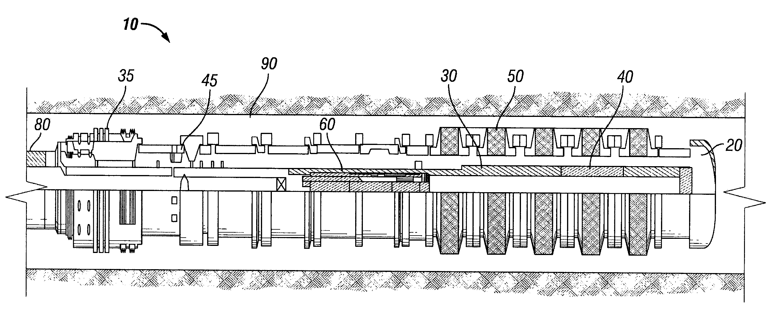
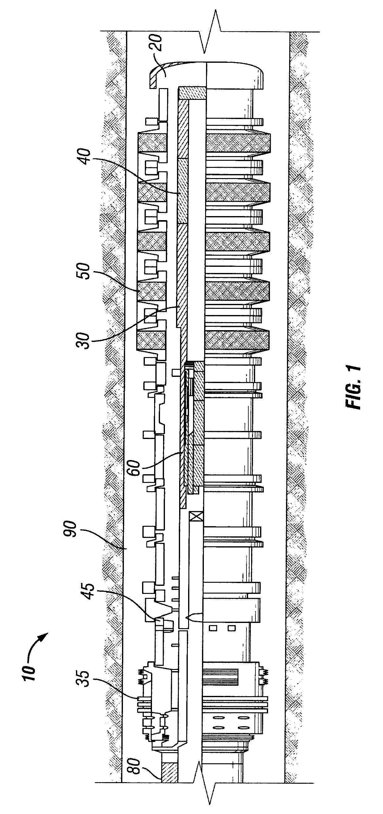
[0021]Referring to FIG. 1, one embodiment of a low drag flotation system (LDFS) 10 is illustrated in a horizontal well 90. A horizontal well, as used in this disclosure, refers to any ...


PUM


Abstract

A low drag flotation system for placing screens in horizontal wells is provided which includes a screen exterior to the washpipe to be placed for sand control, and hydraulically actuated valves for trapping air within the washpipe. The air in the washpipe creates a buoyancy force that decreases the drag force of the pipe string in the horizontal well, allowing it to move further down the well under its own weight. As a result, screens can be placed in longer lengths of horizontal wells to maximize oil and gas production.

Description

BACKGROUND OF THE INVENTION[0001]1. Field of the Invention[0002]The present invention relates generally to a screen placement system for an oil and gas well. More particularly, the present invention relates to a low drag flotation system for placing a screen assembly in a horizontal well.[0003]2. Description of the Related Art[0004]It is often desirable in the oilfield industry to drill horizontal wells to produce oil and gas. Longer horizontal sections maximize oil and gas recovery from these wells and are thus in longer lengths. These horizontal wells may either be cased holes or open holes.[0005]It is also desirable to place screens in the horizontal wells to control the amount of sand entering the wellbore either from an open hole or perforations in a cased hole. This protects well equipment and surface equipment from sand damage. The screen assemblies, either stand-alone or gravel packed, traditionally include a screen with a washpipe inside to facilitate fluid circulation down...

Claims


Application Information

Patent Timeline
Patent Type & Authority Patents(United States)
IPC IPC(8): E21B43/10
CPCE21B43/10
Inventor JORDAN, ANDREW K.VILELA, ALVARO JOSECARVALHO, FREDERICO
Owner SUPERIOR ENERGY SERVICES LLC
Why Eureka
Try Eureka