Swiveling roll bar

Active Publication Date: 2010-03-16
BOMAG
View PDF23 Cites 16 Cited by
  • Summary
  • Abstract
  • Description
  • Claims
  • Application Information

AI Technical Summary

Benefits of technology

[0018]In an especially preferred embodiment, the joint stiffener completely grips three sides of the other spar. This three-sided grip further increases the stiffness of the link joint. Preferably, the joint stiffener is so arranged that its open side corresponds to the side of the link joint nearest to the hinge.
[0019]In a further embodiment, the final control element is constructed as a clamping screw. Preferably, the lock comprises a clamping bolt, which is arranged between the joint stiffener and the screw head and exhibits an opening, through which the threading of the clamping screw is arranged. It is preferable further, if the joint stiffener exhibits a recess in the area of the clamping bolt. Thereby the recess is designed in such a fashion that the clamping bolt of the clamping screw presses against the boundary of the recess. If the clamping screw is loosened, the clamping bolt can be brought into a position, in which it overlaps the recess, so that the joint stiffener is released. On one hand, the tension resulting from the planar support of the clamping bolt can be distributed better on the joint stiffener and on the other hand the clamping screw and the clamping bolt remain firmly connected with the link joint when loosened, so that they cannot be lost.
[0020]It is of advantage, if the clamping screw is constructed as a tommy screw, so that no tool is required to tighten the joint stiffener against the other spar.
[0021

Problems solved by technology

Such an upward jutting roll bar can be disadvantageous, for example, during transport of the vehicle or during its operation.
The disadvantage thereby is that such a catch has some play due to the bolting and that the upper segment of the roll bar can swing out under operation related vibrations.
Moreover, such a connection is difficult to manufacture.
The disadvantage thereby i

Method used


Image

  • Swiveling roll bar
  • Swiveling roll bar
  • Swiveling roll bar

Examples


Example

[0032]In the various embodiments according to the invention shown in the following figures, the same components are indicated with the same reference signs.

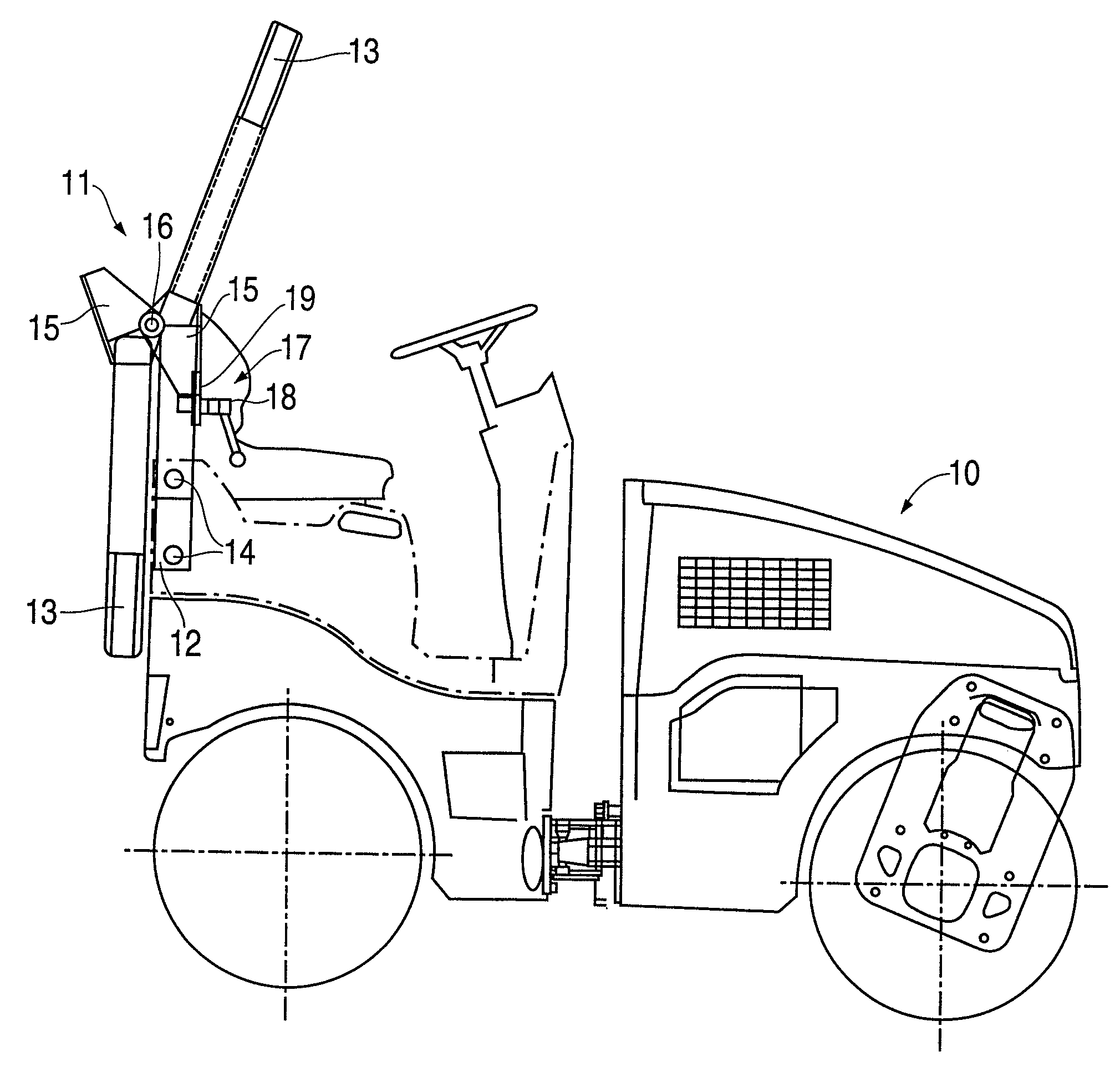
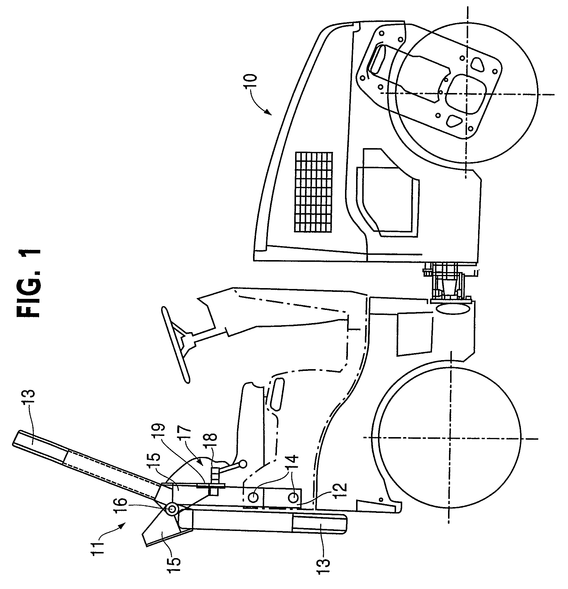
[0033]FIG. 1 shows the side view of a cylinder 10 with a swiveling roll bar 11, which has a stationary spar 12 and a swiveling spar 13. The roll bar 11 is displayed not only in the locked but also in the down-swung state. The stationary spar 12 is fixed with the cylinder frame of the cylinder 10 by means of bolt connections 14.

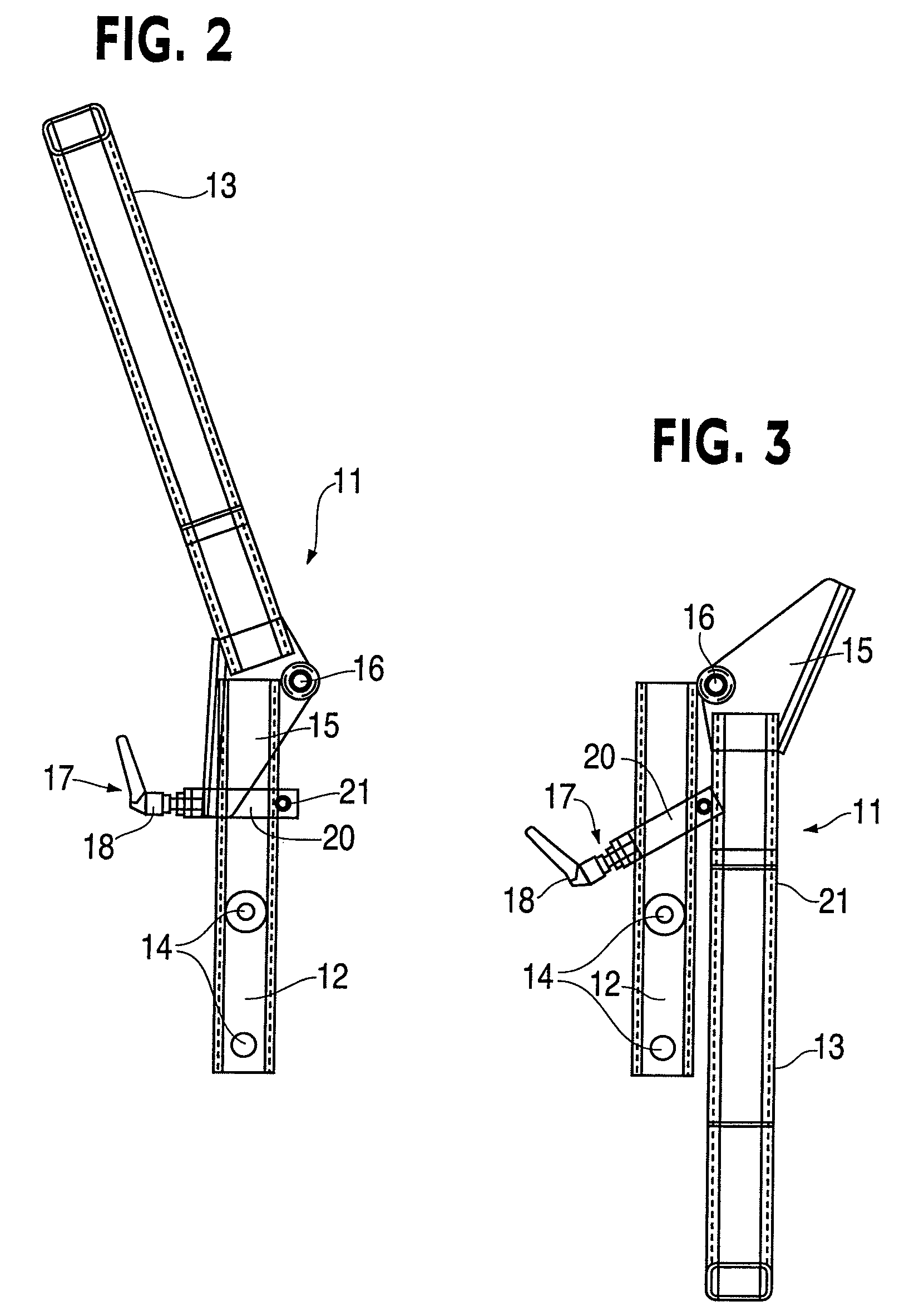
[0034]As it can be seen in FIG. 1, a link joint 15 is attached at the end the swivelable spar 13. The joint stiffener 15 consists, in the shown example, of a U-shaped tubular segment, whereby the U-shaped tubular segment 15 is so arranged that its open side corresponds to that side of the roll bar 11, on which the hinge 16 is attached. The U-shaped tubular segment 15 is welded with the swivelable spar 13 and is connected with the hinge 16, so that the U-shaped tubular segment 15, together with the welded, u...


PUM


Abstract

The invention relates to a swivelable roll bar, in particular for construction vehicles, with two vertical carriers, each of which has a pair of spars, whereby in each, one spar is connected swivelably through a link joint with the another spar, and the link joint comprises a lock and a stop. The stop consists of a joint stiffener, which is built as an extension of one spar and partially grips about the end of the other. In addition to that, the lock has a continuously adjustable final control element, with which the joint stiffener can be braced against the other spar. With the grip about the other spar, the flexural strength of the link joint of the swivelable roll bar is increased. Further, the bracing of the joint stiffener against the other spar eliminates the play in the link joint. The joint stiffener is preferably built as a U-shaped tubular segment that is attached to the latter as an extension of the spar.

Description

CROSS REFERENCE TO RELATED APPLICATIONS[0001]This application claims priority to and is a continuation of U.S. patent application Ser. No. 11 / 086,243, filed Mar. 23, 2005, entitled “Swiveling Roll Bar,” which claims priority to German Patent Application No. 102004014475.5, filed Mar. 24, 2004, entitled “Foldable Rollover Protection System,” the disclosures of which are hereby incorporated by reference in their entirety.FIELD OF THE INVENTION[0002]The invention relates to a swiveling roll bar for vehicles, especially for construction vehicles, with two vertical carriers, each one of which has one pair of spars, which are connected with each other through swivelable link joints. Further, the link joints have both a lock as well as a stop, which limit the swivel area of the roll bar.BACKGROUND OF THE INVENTION[0003]Work vehicles, especially construction vehicles, are often equipped with rollover protective fixtures and roll bars, which are fixed on the vehicle frame and extend upwards,...

Claims


Application Information

Patent Timeline
IPC IPC(8): B60R21/13B62D25/08F16C11/10E02F9/24
CPCF16C11/10B60R2021/134Y10T403/32336
Inventor KURTEN, HANS-WERNERMOTZ, KARL-HARMANN
Owner BOMAG
Why Eureka
Try Eureka