Convertible vehicle

a convertible vehicle and convertible technology, applied in the field of convertible vehicles, can solve the problems of limiting the free headroom of passengers, mechanical parts visible on the inside, and having to be paneled at added expense, and achieve the effects of reducing the parts required for the roof movement, reducing weight, and simplifying the motion mechanism

a convertible vehicle and convertible technology, applied in the field of convertible vehicles, can solve the problems of limiting the free headroom of passengers, mechanical parts visible on the inside, and having to be paneled at added expense, and achieve the effects of reducing the parts required for the roof movement, reducing weight, and simplifying the motion mechanism

US7677635B2Inactive Publication Date: 2010-03-16VALMET AUTOMOTIVE

Image

  • Convertible vehicle
  • Convertible vehicle
  • Convertible vehicle

Examples


Embodiment Construction

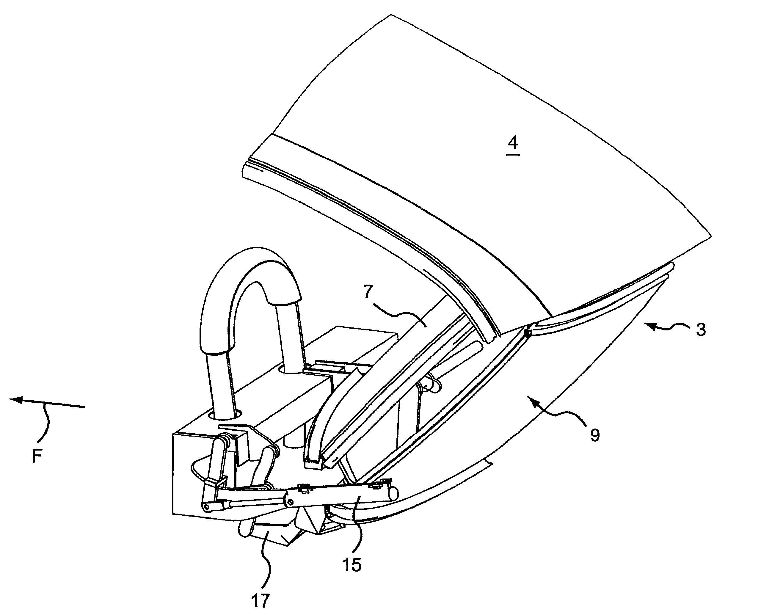
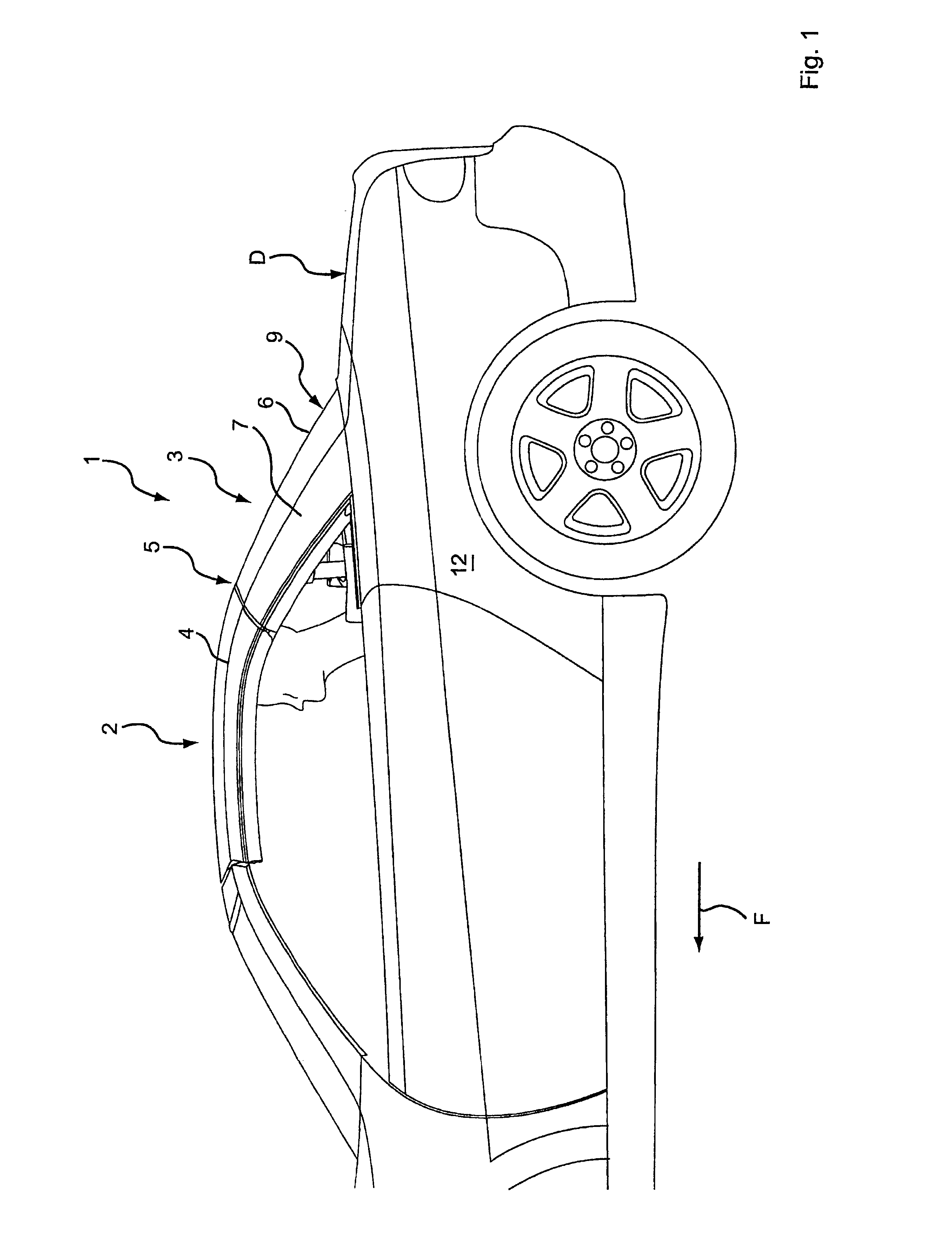
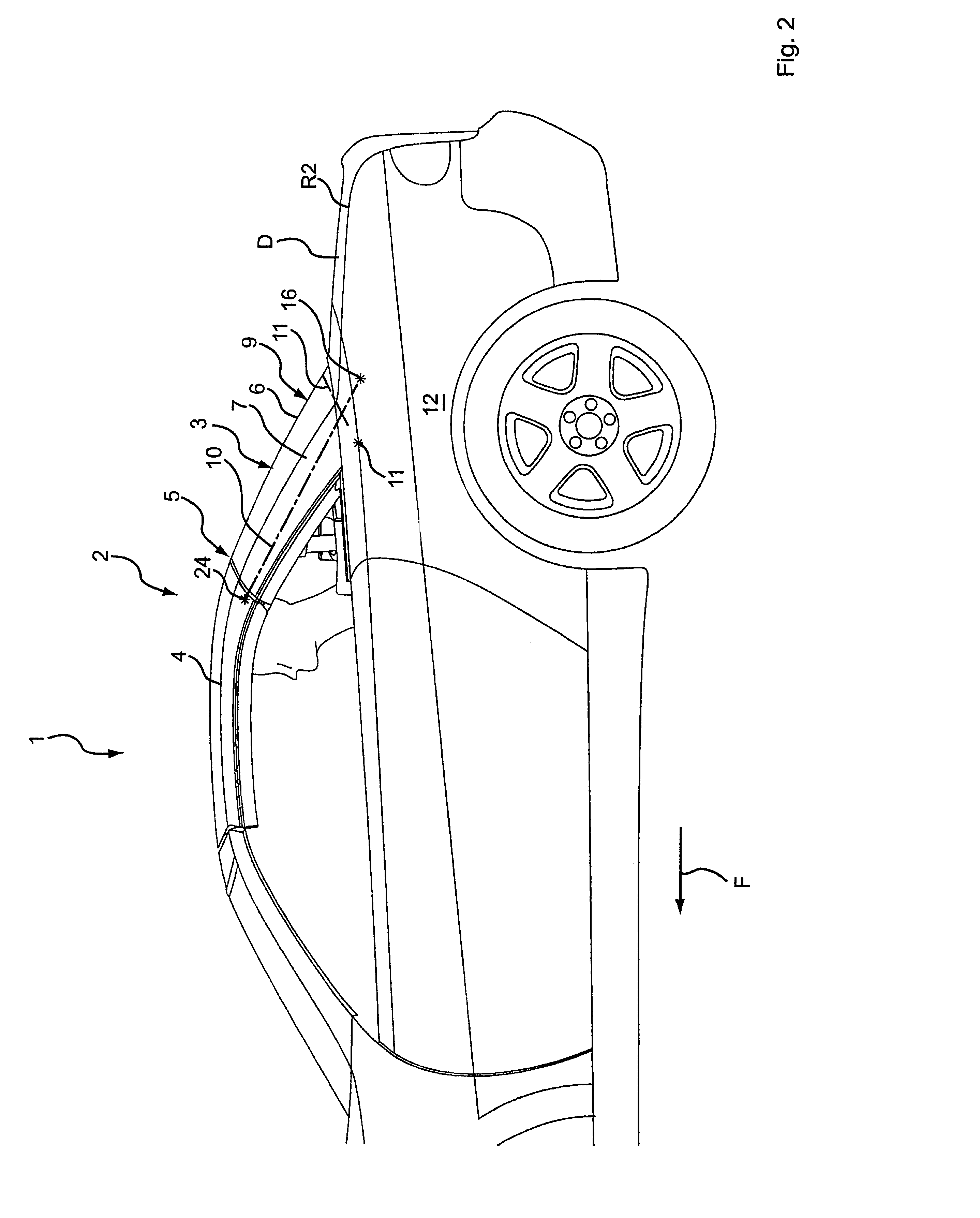
[0049]The convertible vehicle 1 of the invention comprises, in the sample embodiments shown, two roof elements 3, 4 one behind the other in the direction of travel F when the roof 2 is closed and separated from each other by at least one joint 5 lying basically transverse to the vehicle. The rear roof element 3 has a rear windshield 6 in a central segment 9 relative to the transverse direction of the vehicle and extends upwards at a slant. The rear windshield 6 can be the folding kind or, in particular, rigid and consist of plastic or glass, for example. The roof element 4 is arranged in front of the rear roof element 3 in the closed condition (FIG. 1) and lies essentially horizontal. One or more additional movable roof elements can be movably joined, say, to the front roof element 4, for example, they can be linked to it. Therefore, the convertible vehicle 1 of the invention can either be a two-seater or comprise a larger passenger compartment with two or more seat rows one behind ...


PUM


Abstract

A convertible vehicle is provided with a rear windshield and a rear roof element that laterally comprises C pillars that are at least substantially located next to the rear windshield, adjoining which is at least one front roof element, arranged upstream thereof in the direction of travel when the roof is closed. In order to open the roof the rear roof element can move rearward and downward, and the front roof element can swivel toward the rear roof element. When the roof is open, the C pillars can be swiveled inward in relation to a center section comprising the windshield about axes into a position lying above the center position when the roof is open, and the axes when the roof is closed have at least one component in the direction of travel and one upwardly directed component.

Description

CROSS-REFERENCE TO RELATED APPLICATION(S)[0001]This application is a US National Phase of International Application No. PCT / DE 2005 / 000806, filed Apr. 30, 2005 which claims priority to German 10 2004 021 576.6, filed May 3, 2004. The entire contents of the above identified applications are incorporated herein by reference.TECHNICAL FIELD[0002]The invention concerns a convertible vehicle with at least two roof elements as well as a corresponding roof.BACKGROUND OF THE INVENTION[0003]There are known convertible vehicles, which have two consecutive roof elements in the closed condition, one of which, the rear element, can swivel downwards about a transverse axis in relation to the car body, so that in the stowed-away condition it lies essentially horizontal and with its side facing the passenger compartment pointing upward when the roof is closed. The front roof element when opening the roof can swivel onto the rear roof element about a second transverse axis situated in the boundary r...

Claims


Application Information

Patent Timeline
16 Mar 2010
Publication
US7677635B2
IPC
B60J7/08; B60J7/14
CPC
B60J7/0076; B60J7/145
Inventors
BROCKHOFF, FRANZ-ULRICH